Hi Guys, I’d really appreciate some help with an arduino-based project I’m working on. Whilst I’ve been playing with Arduino for a few years now, I’m fundamentally a Mechanical Engineer, so my understanding of all things software and electronics is basic.
I am attempting to use an Arduino Uno R3 to communicate with the following 2 sensors via I2C, but I’m struggling, having never used either sensor, or I2C, in the past. Hopefully it’s something simple and stupid that I’ve done wrong, but I’ve done a fair bit of reading around online and am yet to find a solution.
The setup is as follows:
• Arduino Uno R3
• MPU6050 Digital Motion Processor, on a GY-521 breakout board. I will ultimately be using this to try and stabilise a home-made camera gimbal. For now I’m just looking to read the values from the DMP, I’ll deal with the processing and control system later on.
• Pixart IR Camera (“WiiCam”) from Nintendo Wii remote. This will be used to track an infrared light source.
Here is what I’ve tried to date:
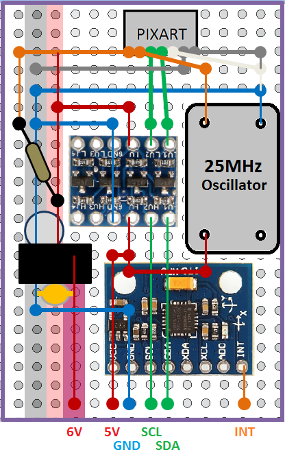
- I first got the WiiCam working with Arduino, by following steps and instructions found here, along with the code found here. I made the circuit shown in attachment 1 on a breadboard and it was an immediate success – the camera works great!
- Then I got the MPU6050 working on a breadboard by connecting it as shown in attachment 2 and using the example code found in Step 2 here. I tested both raw and DMP outputs and everything works as expected.
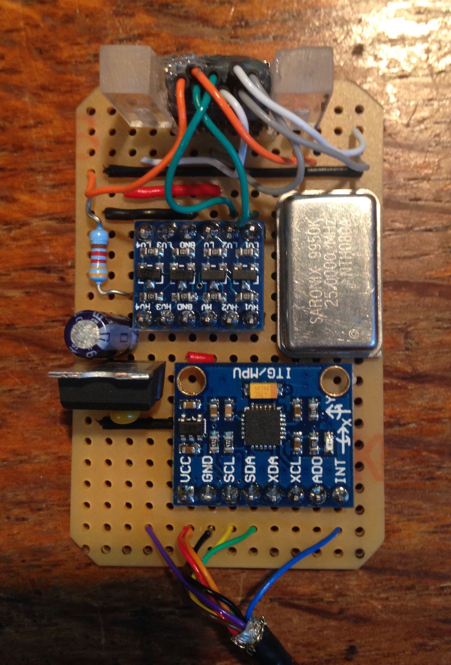
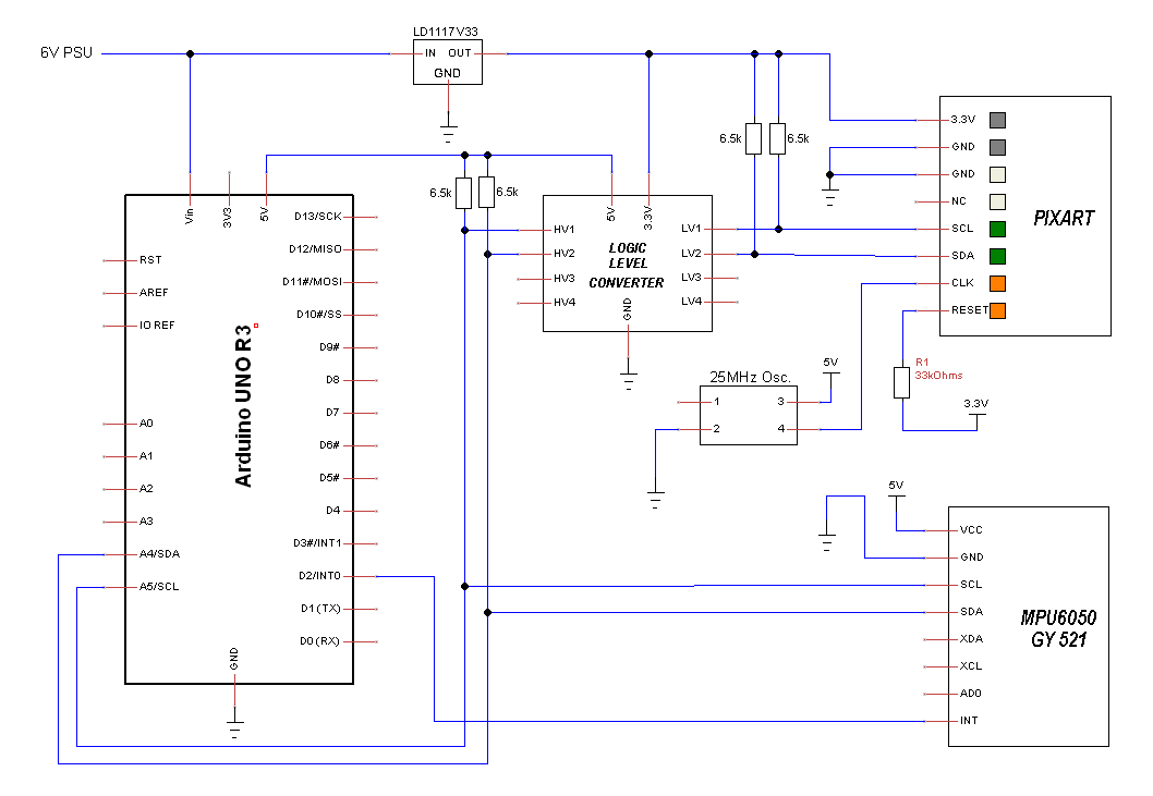
- This is where I got cocky. Having successfully got both components working separately, and having researched the basic theory behind I2C, and how to connect masters and slaves together, I then designed and built a circuit using stripboard and soldered everything together, as shown in attachments 3 & 4.
- Using the same code as in step 1, I checked the WiiCam still works – success! No problems with the WiiCam whatsoever.
- However, the MPU6050 is a different beast, and is not playing ball. Using the same code as in Step 2, it does not work as part of my soldered circuit. This is where you come in (hopefully)!
So my initial thoughts on the problem were as follows:
- Maybe the addresses of the 2 slaves are the same. I downloaded this code to find out. This successfully found both devices; MPU6050 = 0x68 (I understand I could change this to 0x69 if necessary) and Pixart camera = 0x58, so this shouldn’t be a problem.
- Maybe I have somehow broken the GY 521 board during the soldering process. To test this, I de-soldered it from my circuit and tested again with the breadboard. All works fine – no problems.
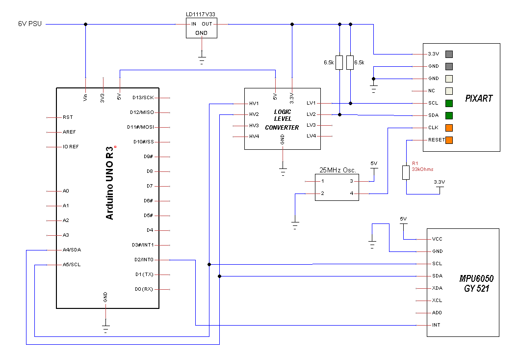
- I’d forgotten pull up resistors, so I added some. I only have 6.5k or 16k, so tried the former. I added some on both the 3.3V side and the 5V side, as shown in attachements 5, 6 & 7, but no difference
- Maybe my 1m length of wire is adding impedance (?) and causing problems. Or maybe another part of the circuit is interfering (i.e. the 25MHz oscillator) in some way. To test both of these, I soldered the GY 521 back into the circuit but disconnected the SDA and SCL lines of the WiiCam. The problem now vanishes – the DMP works fine!
I now wonder if problem may be one of software. I understand that the GY521 stores data in a FIFO buffer and uses an interrupt signal to tell arduino when there is data ready (to prevent buffer overflow). What I don’t understand is how and if the Arduino decides to request/receive data from the Pixart. Could it be trying to do this in the background and throwing off the MPU6050 ISR?
It’s worth noting that the problem occurs during initialisation of the DMP, I simply receive “DMP Initialization failed (code 1)” error on startup, as shown in attachement 8. I have also tried receiving raw values from MPU6050 with the example code from the same library – I am sometimes able to get raw values for 2-3 seconds, but then it ‘crashes’ and no more data.
Any suggestions for things to try next would be really appreciated. If you would like any more information, I’m happy to provide it.
Thanks,
Tom