Hi all,
I want to choose between an Arduino with built-in DACs and an Arduino paired with an external DAC chip. My circuit must work with higher frequencies (more than 200kHz) and be high speed. Which method is better? and why?
How can I find out the maximum output frequency of an Arduino microcontroller through their datasheet?
- What exactly are you doing.
-
Did you look at the controller data sheets for the different Arduinos ?
-
Most of the Arduinos do not have a DAC.
There are a lot of possibilities but I am not in a position to recommend any solution as you are missing just about everything needed to make a proper selection. Do some research and find something you like, then post that with your reason and what requirements it has and doesn't have.
I have LED illumination project in that I should control the LED current by changing the voltage source with an Arduino. We need the LED illumination for a camera detection response to know how long exactly it will take for the camera to detect the illumination. We should also control the light of LED in a sinusoidal manner to measure the time response of camera.
So I need a precise DAC that could create high-frequency voltages.
I want a 16-bit DAC and looked for Arduinos that have built-in DACs. Finally, I found the ESP32 with two 8-bit DACs that I can integrate to create a 16-bit DAC. But I don't know how much frequency it can create for me.
So, I am also looking for external ICs. maybe that could create this amount of frequency. Although it can cause some problems for me.
specification is vague
do you require a DAC which can be updated 200000times/second?
do you wish to generate waveforms of 200KHz?
square, sine, ramp, arbitrary???
why 16bit?
generally recommended to use microcontrollers with onboard DACs as this removes the problems associated with wired interconnections
I want to generate waveforms with frequencies higher than 200KHz. But I want to make sure if the Arduino I want to buy, can create this amount of frequency or not. How should I know this feature just through their datasheet?
I want 16-bit for more precision.
I also want to generate all of the square, sine, ramp.
have a look at DDS modules, e.g. arduino-ad9833-signal-generator-dds-function-generator
EDIT: also have a look at stm32-dac-sine-wave-generation-stm32-dac-dma-timer-example
2 Likes
PWM is a working method for controlling LEDs.
1 Like
That is not the way to control an LED because it is not at all liner, and only a small range of voltages will control any brightness at all.
PWM is the way to go, but PWM brings its own problems unless you take measures to mitigate them. The problem is that the PWM frequency used by default is too low. So you first have to increase the speed of the PWM to something like 40KHz or so, before you use it.
If you intend to create photography or video lighting with LED i understand your desire for a voltage controlled solution. PWM will cause flickering. The best i can think of is the ESP32 as you have already found. About the speed requirements, i think it should be fast enough for your purpose. The DACs are intended for sound generation and the controlling thru the I2S happens fully in the background.
Another option could be a SPI-DAC like DAC8830 which is 16 bit. I can ot really help you much with any of the coding, but even so. An ESP32 isn't that expensive and will give you the possibility to create a webserver to be used as a UI which will avoid the use of all sorts of buttons.
Is this some kind of ultra-high frame rate video camera?
How come the manufacturer's specifications of the camera aren't sufficient?
What exactly are you trying to establish?
No, but they could feed the output of a DAC into a VCCS and modulate the LED that way. The VCCS could be something conceptually simple like an opamp-based servo with a shunt resistor for current sensing. How to approach this would depend on myriad requirements that are currently unspecified, such as desired response time, acceptable levels of noise and required LED power.
1 Like
In theory yes, in practice, not a practical solution.
1 Like
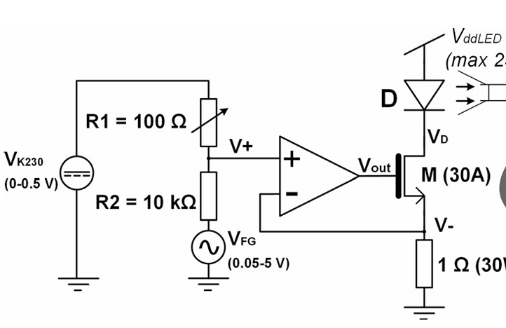
This is my circuit. I have tested this circuit and found the input voltages with the equivalent value of LED current. Now I want to remove the DC source and put an Arduino board to generate that amount of voltage for me. Sometimes I want to keep the LED current on a predefined voltage by Arduino. Sometimes I want to generate step waveform currents. But something like DAC should be there to generate that amount of voltage for us. In total, we want to put a camera in fornt of the LED to measure the time takes for the camera to detect the waveform.
yes only the voltage range between 0 to 0.48v can control the brightness and we have the current only for this amount. Do we have any other way to have more voltage ranges?
I preferred to choose DAC because it was more accurate than PWM and doesn't have the PWM problems.
Thank you so much. Yes, I think ESP32 is a good option. But someone said that it can not be practical. From the theoretical point of view it is possible. Can't we integrate the two 8-biys DACs to create a 16-bit DAC?
It is completely impractical and utterly pointless, especially so if you have to ask how to do it.
1 Like
the ESP32 can also do BT, WIFI and are way faster than an Arduino, at 200MHz, but that's beside the point.
DACs... I think it's possible to get away with not using a DAC, I did before, by using 65kHz PWM, as for quality, DACs are ideal.
1 Like
Thank you for your insight. My problem here is that I just can control the LED brightness only for voltages between 0 to 0.5v which is a small range! In that way, the currents are between 0 to 400 mA. But for the next stage, we need more current for LED even about 1A. Do you know how can I do this?
There is nothing in your post justifying any of this effort. The approach and specifications make no sense to me, and seem to have been plucked out of thin air.
Please describe the research have you done to determine how many levels of brightness are actually required, and the results. Clearly describe how and why you have determined that such high frequencies are needed.
2 Likes
No.
This is because in order to do this each of the DACs need to have an accuracy of a 16 bit DAC, and there is simply no point in doing this for manufactures of DACs.
The normal accuracy of a DAC is often quoted as being monotonicity. This means that for every increase in the digital value input by one, the output must go up or at least stay the same. Of course this also applies to going down as well. That is for every decrease on the input by one the output must drop or stay the same. This diagram shows this:-
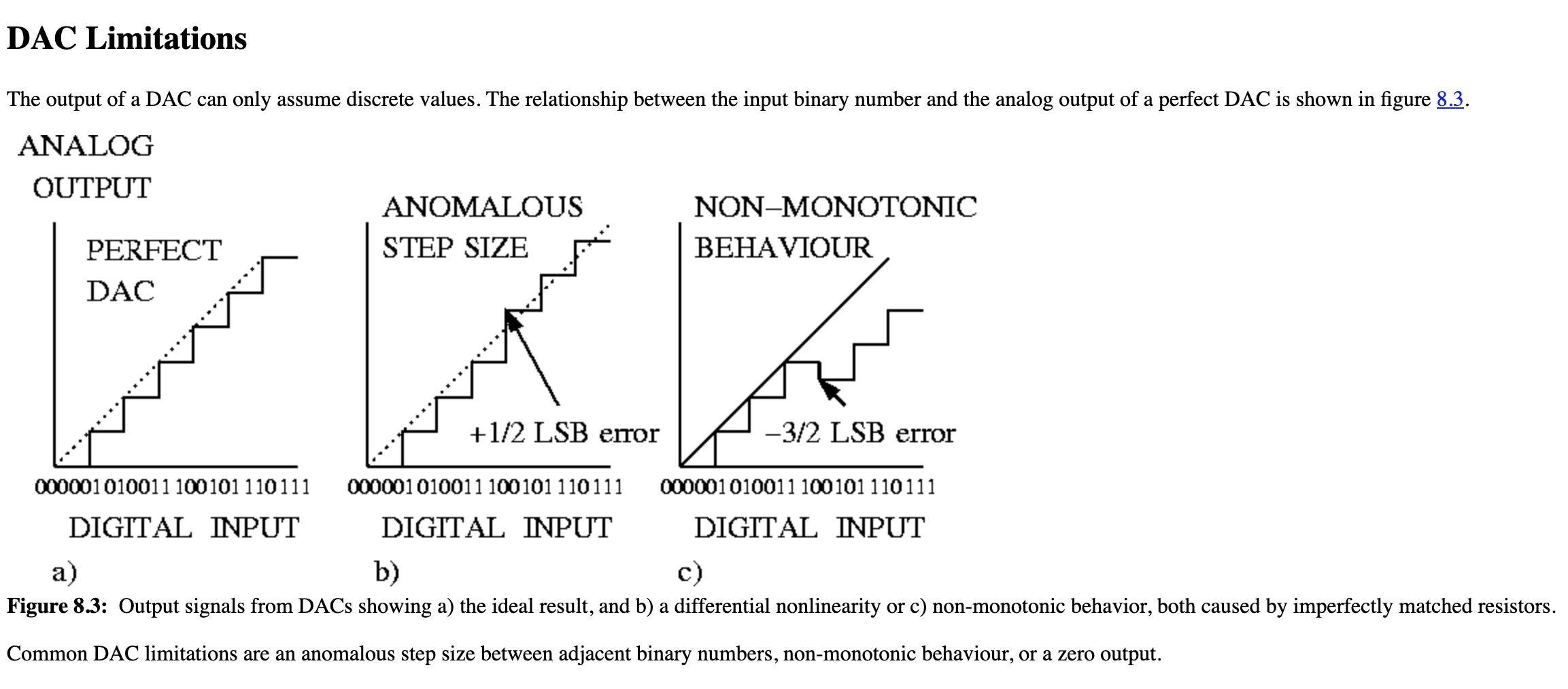
So hopefully you can see that you can't combine two 8 bit DACs together to make a 16 bit DAC because the 8 bit DACs are simply not accurate enough.
Now from the diagram in your post#14 it is clear that this is no ordinary LED. So what exactly is it?
Does it consist of one large power LED or is it several power LEDs in parallel?
When dealing with power LEDs you have to treat them as a current source and drive then with a constant current driver. This is fine for a single power LED, but becomes a bit of a nonsense with several power LEDs in parallel, because each of the LEDs need their own constant current driver. I suspect that this light was never designed to be dimmed in the first place.
Well not an 8 bit one, I would go back to a 16 bit one, given of course, the caveats above.