I have been hunting around for weeks to try and find an Arduino that has a higher quality oscillator (crystal rather than ceramic maybe) for a more accurate Millis.
My project involves between 8 and 32 countdown timers between 1 and 24hours long. They don't have to be precisely accurate, just within say 5mins in 24hours. The device will be outside in IP67 enclosure so will in some way be affected by temperature. I'm currently using SoftTimers library and I do understand Millis will roll over after 45ish days and will account for that.
I do not need/want a RTC as I am not interested in keeping actual time, just the countdown. I also want the countdown to stop if power is out (as relays will have stopped too) and resume from close to where it left off (probably writing remaining seconds to EEPROM every 15mins as a backup). The only benefit I would be getting from a RTC is its better oscillator and maybe temp controlled adjustment.
I know everyones immediate thought is that "if you need accurate time use a RTC". But I don't want to have to add another component to the mix, I don't need actual time and it doesnt need to be that accurate (<5mins per 24hours). I also don't want to get time from GPS, GSM or Radio as will mean additional components.
So my question is....can anyone suggest an Arduino Uno or similar board that has an oscillator accurate enough to meet this requirement without additional components and without me having to build a custom board?
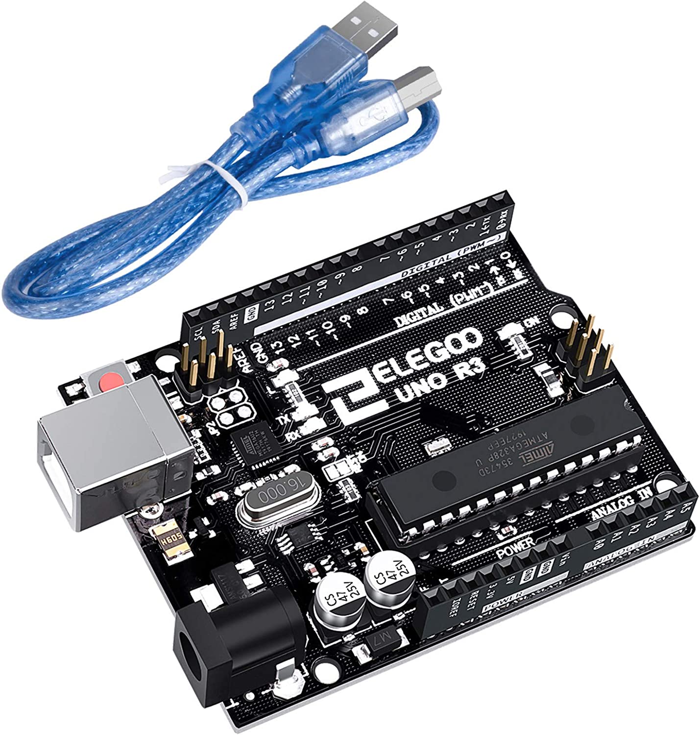
The regular Arduinos are as far as I know typically about that accurate (did you actually try this with your board?). The Uno clone that I have in my drawer actually has two crystals - one 12 MHz for the USB chip, one 16 MHz for the ATmega328P. I've never tried it, tbh, as I've never had your set of requirements - for me typical cases are: a few % off is irrelevant, I want a stable clock (where the actual frequency is less important as it just has to be stable - that's where a crystal comes in), or I need actual, accurate time so adding an RTC.
If you do it properly, you don't have to worry about millis rolling over at all.
In the testing I did against a DS1302 at inside room temp an Elegoo Uno was about 1m4sec slow after 9.5 hours (attached). This is OK I suppose but likely to be much worse outside and not great.
I just don't know why we cant buy an Uno with a proper crystal? Do you know of any?
mypi-home:
In the testing I did against a DS1302 at inside room temp an Elegoo Uno was about 1m4sec slow after 9.5 hours (attached). This is OK I suppose but likely to be much worse outside and not great.
It's well within your specification.
Why do you think it will be worse outdoors? Did you try?
I just don't know why we cant buy an Uno with a proper crystal? Do you know of any?
As said, I have one... Uno with crystal... bought mine about 4 years ago, I had to pay RMB 20 for it. Gotten quite a bit cheaper!
You say you've been looking for weeks? Where have you been hunting? You do have to do a little digging, but the full schematics and parts list are available online for all the official Arduino models. The Pro Micro has a crystal oscillator, for example. If you look on any online store like AliExpress or Ebay, you will find hundreds of UNO, Nano, clones ... many of them have replaced the ceramic resonator with a crystal part. You can easily see the difference visually. The crystals come in a different package.
Here's one example of an UNO clone with quartz crystal:
Not a product recommendation, just showing you what you can obtain.
Add an RTC to your circuit. YES! I did read that you don't want to, but
you can configure the RTC to produce a 1 Hz square wave. You don't need to hook it up in any other way (I2C, whatever) after you have configured it, just connect it to power, ground and listen on an input pin to the 1Hz signal either by polling or interrupt. It's so slow that you ought to be able to do it by polling in the loop(), it's a clean signal so just watch for the transitions.
Count those and you have a very accurate measurement of the passage of time.
If you're truly desperate, you can program the UNO onboard 16U2 with custom firmware to produce a PPS signal. It does have a crystal oscillator, so it can produce a reasonably accurate timebase.
On the RTC square wave I am aware of that but still requires a new component which I want to avoid. Why cant the Uno just keep Millis time as accurately as a RTC with the right oscillator?
Perhaps that silver thing already is a crystal oscillator in which case the question is can I can one with a more accurate oscillator? Everything I read says the Uno has ceramic one. I've search loads on AliExpress and other sites and couldnt find anything specifically saying crystal or more accurate millis.
This was the code I used to check the clock drift over time in case that is somehow the issue:
If this is just for your one copy, perhaps you could calibrate your Arduino. You have Timer1 available, which is a 16-bit timer. You could select the Timer1 rollover value that would let you be accurate to within about one second in 24 hours, which is better than any RTC would give you. That's not accounting for temperature, so you would have to test for that. And by the way, I don't think a DS1302 is a good standard to measure against. RTC crystals aren't all that accurate.
You have to look for a board with two crystals: one is for the USB chip (I see an SMD part with Atmel on it, I guess that's the 32U2 taking care of the USB connection, no doubt the crystal belongs to that chip) and is present on all boards, and one for the ATmega328P. Just as you can see in the links I and aarg posted.
It seems that the Unos using the DIP package of the '328P tend to have a ceramic oscillator; the clones that use the TQFP package often (but not always) have a second crystal oscillator.
Anyway, you obivously have to search a bit harder.
And just having a board with a "crystal" does not make it accurate. The entire circuit, including the crystal must be enclosed in a temperature controlled environment. Then there are the voltage changes that occur and make the oscillator change frequency. All must be controlled before you get close to an accurate and stable frequency.
Paul_KD7HB:
And just having a board with a "crystal" does not make it accurate. The entire circuit, including the crystal must be enclosed in a temperature controlled environment. Then there are the voltage changes that occur and make the oscillator change frequency. All must be controlled before you get close to an accurate and stable frequency.
Paul
That is true. However these factors probably exceed the OP requirement as it was stated.
I don't want to have to add another component to the mix, I don't need actual time and it doesnt need to be that accurate (<5mins per 24hours).
nicolajna:
You can desolder the one that's already there and solder on the one you want?
I don't recommend it. The PCB pads for the resonator are hidden under the part, which makes removal a dicey operation (even when you heat the entire part). Then you have to kludge on the crystal leads. Definitely not worth the trouble.
Section 8 of the ATmega datasheet shows how to connect a crystal. I think you have to add a pair of capacitors and it might get a little "messy" but I'm pretty sure the board can be modified.
The CSTCE16M0V53-R0 16MHZ resonator on the Uno is specified at 0.5% accuracy (before temperature and aging considerations). Crystals are typically 50 - 100 ppm. Watch crystals are "trimmed" (with capacitors?) for better accuracy. And I assume the same is done with RTC modules (at least the "good ones" ).
Of course, computer & phone clocks are re-set frequently over the network, usually from an atomic clock somewhere on the Internet. GPS satellites also have atomic clocks so anything with GPS can get "perfect time". Mechanical AC powered clocks use a synchronous motor locked to the power-line frequency (50 or 60Hz) . The power line frequency in most countries is super-accurate and errors/variations are corrected-out so a mechanical clock can remain perfectly accurate for years, until there is a power failure. (Some AC-powered digital clocks also use the line frequency but I think (less accurate) crystals are more common.
To follow up on my suggestion to calibrate your Arduino, shown below is code I wrote a while back to disable the stock millis() function, and instead use one that increments once every ms. The stock version uses the 8-bit Timer0 overflow at 255 to generate the interrupt, but that's too slow. So every now and then, it increments the millis() value by 2. The replacement overflows at 249, which provides an interrupt at exactly the right time, so no doubling up is needed. That's if the crystal or resonator is accurate.
You could use similar code, but use Timer1 instead, which is a 16-bit timer. Through experimentation, you could find the Timer1 overflow value that gives you essentially perfect time. Moreover, the 328P's ADC module has a temperature sensor. So after additional experiments, you could have your software set the overflow value based on the temperature reading.
You would have some datasheet studying to do on Timer1 and the ADC, but I think this would give you essentially perfect timekeeping at any temperature with no additional parts. This method would let you adjust the timing to within one part in 65536, and there are only 86400 seconds in a day.
/*
This is a replacement for the ISR(TIMER0_OVF_vect)
interrupt that drives millis(). It disables the OVF
interrupt, enables the COMPA interrupt, sets OCR0A to 249,
and changes Timer0 to CTC mode.  This results in an
interrupt every 250 timer clock cycles, which is exactly 1ms
for a 16MHz crystal, or 2ms for an 8MHz crystal.  The new ISR
increments millis, but since the interrupt rate is exactly
correct, no periodic double increment of millis is needed.

Using this code probably means you can't do any analog
writes that use Timer0, which would include pins 5 and 6.
*/

extern volatile unsigned long timer0_millis;   //these defined in wiring.c
extern volatile unsigned long timer0_overflow_count;

volatile unsigned long MILLIS_INCB = (64 * 250) / (F_CPU / 1000);  // ms between timer overflows

const int cycleTime = 500;                 // flash LED every second
int LEDcount = cycleTime;
unsigned long oldMillis = millis();
unsigned long newMillis = 0;

void setup() {                             //Set up alternate interrupt
                                           //   at 249 on timer0

  cli();                                   // disable interrupts while doing this

  TCCR0A = 0;                              // set entire TCCR0A register to 0
  TCCR0B = 0;                              // same for TCCR0B
  TCNT0  = 0;                              // initialize timer0 count to 0

  OCR0A = 249;                             // set top of counter
  TIMSK0 &= ~bit(TOIE0);                   // disable overflow interrupt
  TCCR0A |= bit(WGM01);                    // turn on CTC mode
  TCCR0B |= (bit(CS01)+bit(CS00));         // Set CS00&CS01 bits for prescaler = 64
  TIMSK0 |= bit(OCIE0A);                   // enable timer compare interrupt

  sei();                                   // enable interrupts

  pinMode(13,OUTPUT);
  digitalWrite(13,HIGH);

}


void loop() {                               // flashes LED for 1/2 second
                                            //    every second

  newMillis = millis();
  if ((newMillis - oldMillis) > 0) {
    oldMillis = newMillis;
    LEDcount -= 1;
    if (LEDcount == 0) {
      digitalWrite(13,!digitalRead(13));    // invert pin 13 state
      LEDcount = cycleTime;
    }
  }
}


ISR(TIMER0_COMPA_vect) {                    // this is the new ISR - much
                                            //   simpler than original

  timer0_millis += MILLIS_INCB;
  timer0_overflow_count++;

}
aarg:
I don't recommend it. The PCB pads for the resonator are hidden under the part, which makes removal a dicey operation (even when you heat the entire part). Then you have to kludge on the crystal leads. Definitely not worth the trouble.
It's not bad. If he feels that he can't handle the size of the component he can just cut the traces. As for the new one he can solder to the DIP socket on the back of the board.
nicolajna:
It's not bad. If he feels that he can't handle the size of the component he can just cut the traces. As for the new one he can solder to the DIP socket on the back of the board.
From the original post,
can anyone suggest an Arduino Uno or similar board that has an oscillator accurate enough to meet this requirement without additional components
...also I don't recommend that anyone start cutting traces on any PCB until they've reached at least intermediate level electronics skill.
Many Arduino cases have no clearance for any large components on the back of the board.
aarg:
From the original post,
...also I don't recommend that anyone start cutting traces on any PCB until they've reached at least intermediate level electronics skill.
Many Arduino cases have no clearance for any large components on the back of the board.
It was just a suggest which he can follow if he feels comfortable with it, or choose to ignore if he doesn't.