EDIT: Problem solved. The problem was two fold: Weak connections during tests, and pin locations shifting between prototype and this version.
Hello All.
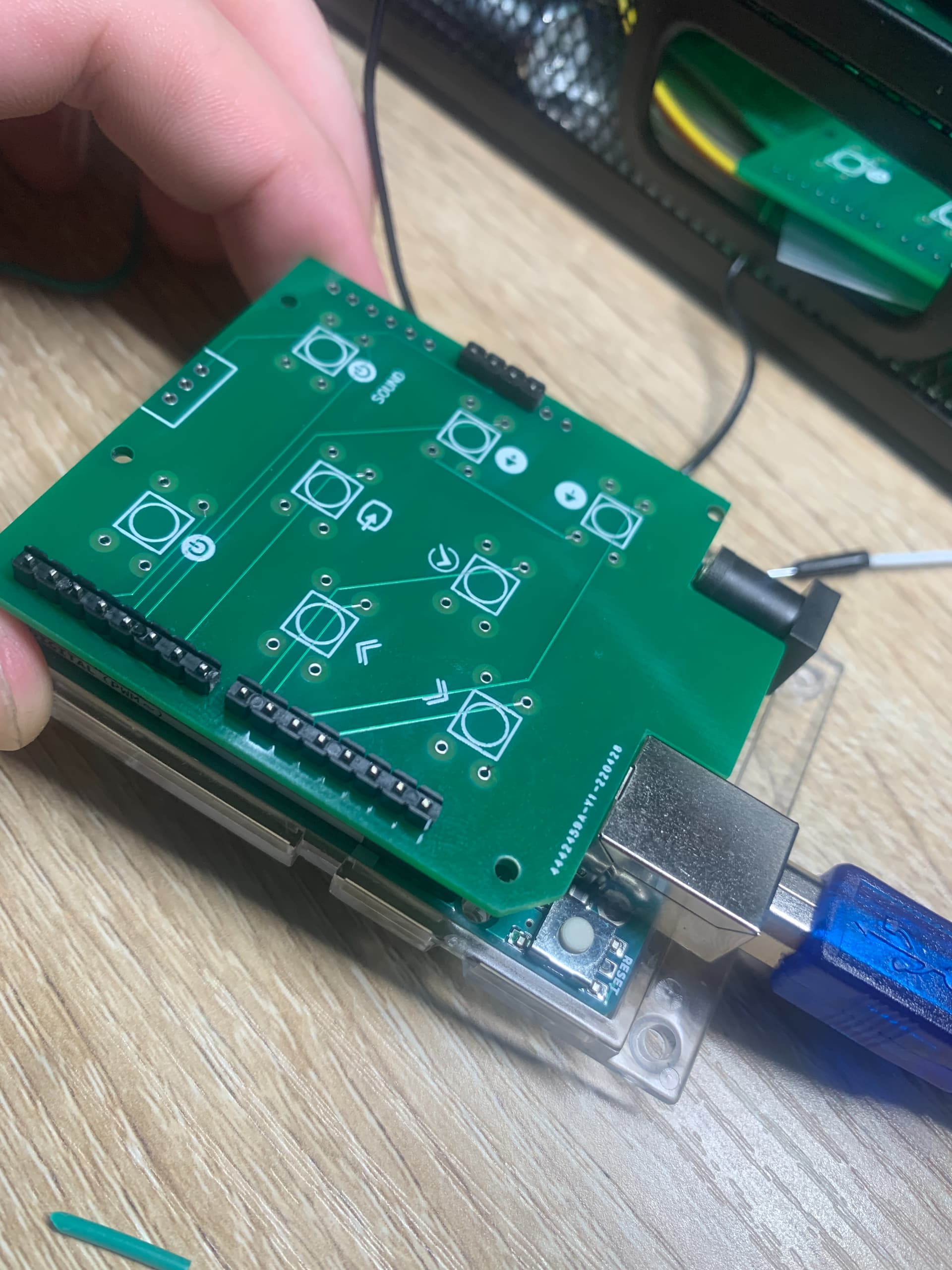
I just got my first-ever custom PCBs. Super excited and they look great, but they're not working.
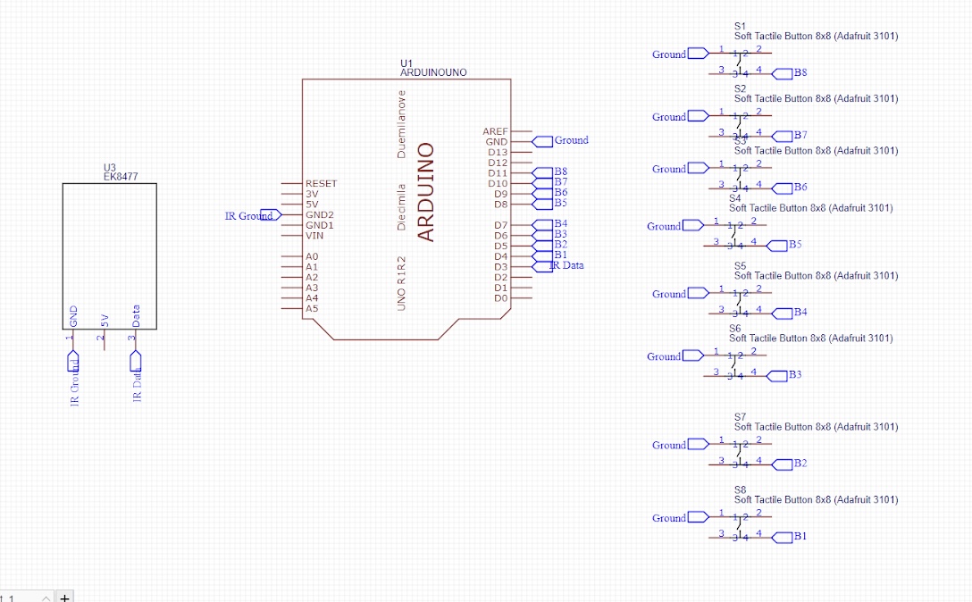
The project is simple: Turn an Arduino Uno into a TV remote. I'm using the internal pull-up resistor on the input pins, and connecting the other side of the button to ground.
All of this has been tested and works awesome... except with my shiny new PCB. The signal doesn't seem to be getting through. (Luckily, I tested this with cables before tediously soldering on all the buttons.)
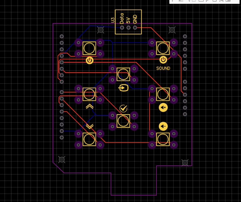
Maybe my tracks are to narrow? They're at the default: 0.254 mm.
Thanks for the reply madmark. Here are the added deets:
It is an eight-button IR remote for my entertainment system. Quite simple: Press one button, my TV turns on. Press another button, my sound bar turns on.
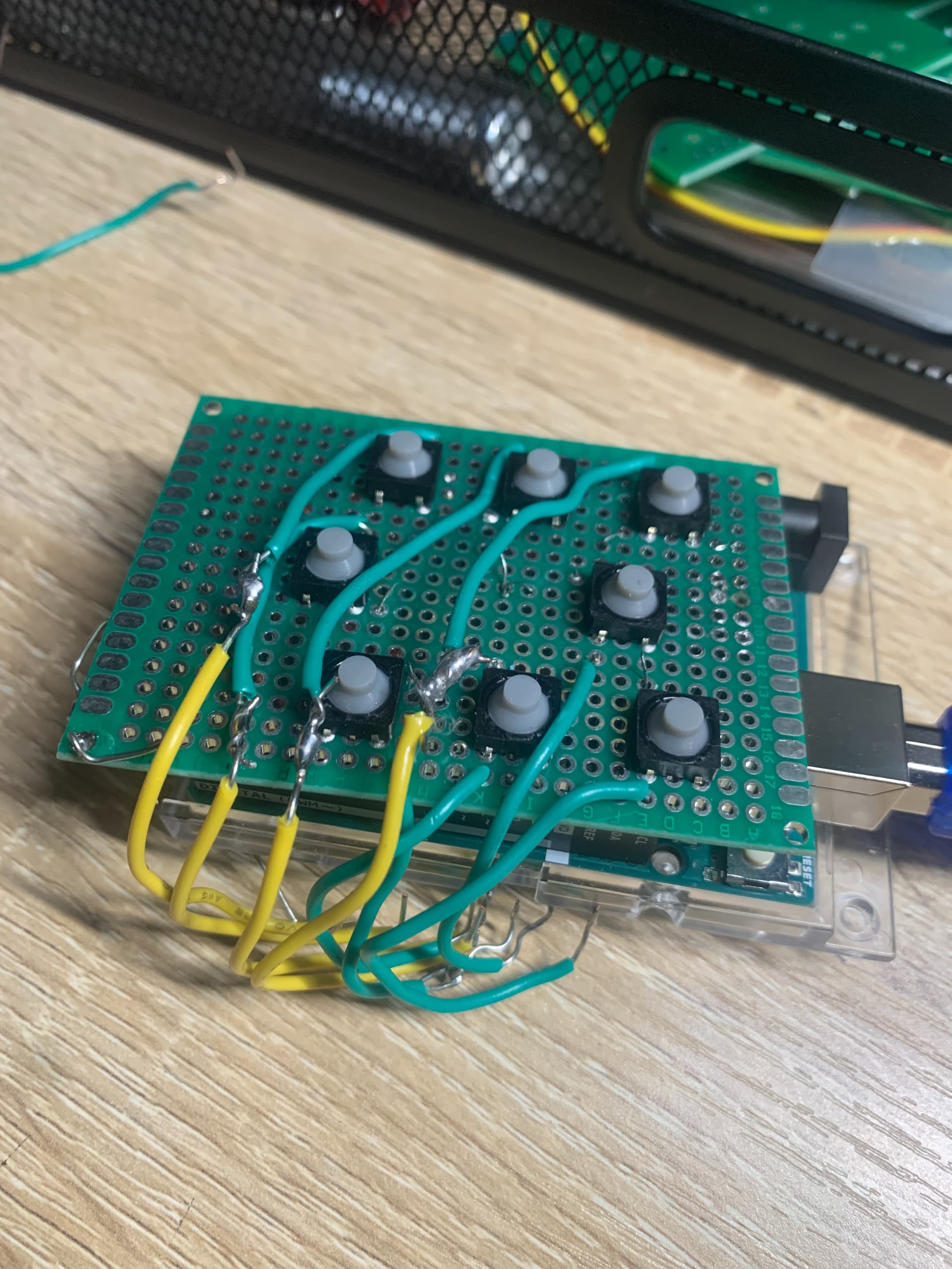
To clarify, the sketch has already been successfully tested with this janky prototype:
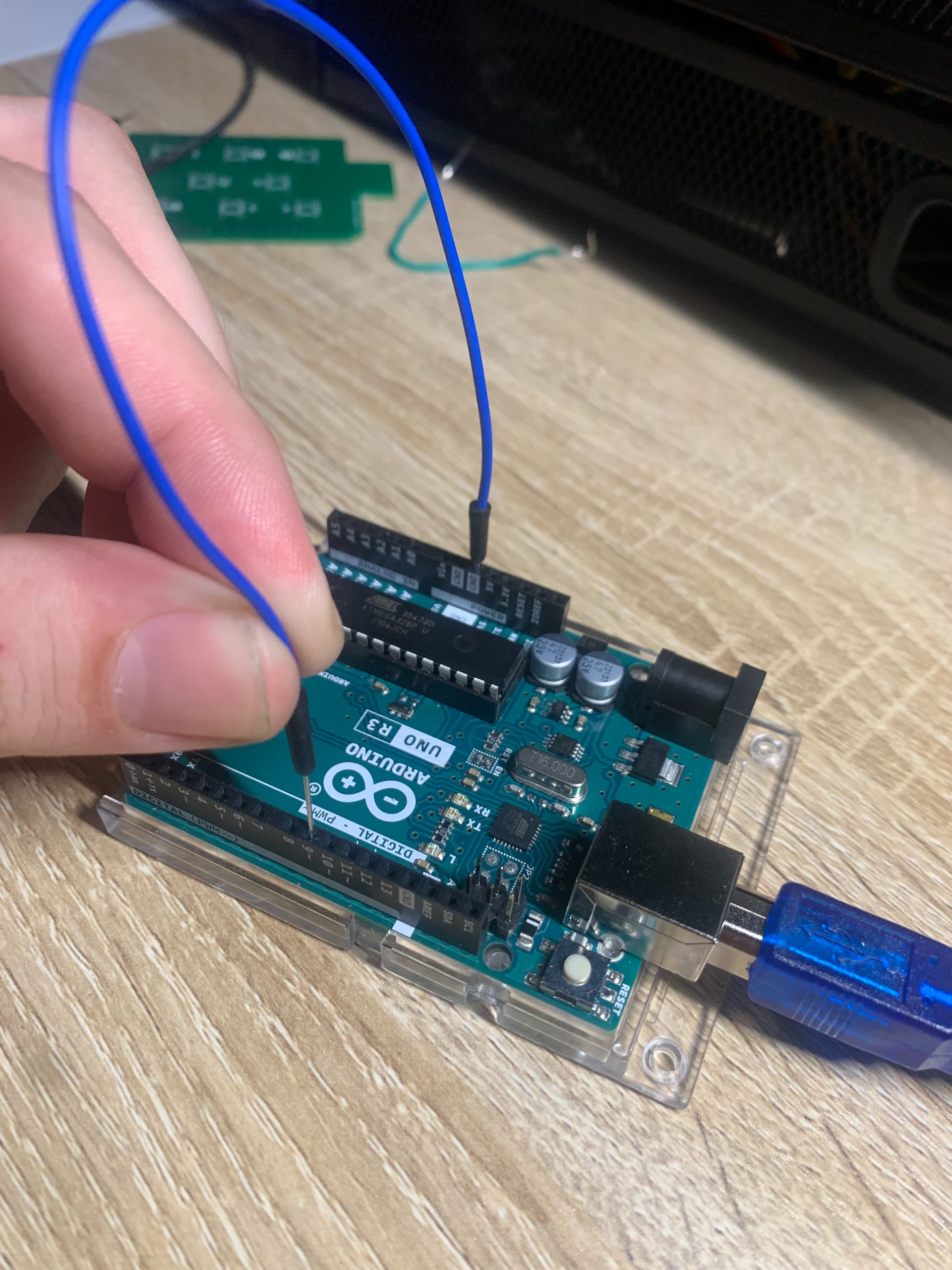
Everything works great. I can also successfully simulate a "button press" by simply touching a wire between any of my inputs and the ground pin, like this:
Again: Success. Arduino detects the voltage drop and runs the appropriate code.
So we're all good there. The problem arises when I try to replace the prototype with the PCB. When I simulate a button press by connecting the appropriate terminals (Button Pin and GND), nothing happens.