AS5311 position sensor with OLED display

Hello,

I am working on a project to interface an AS5311 linear position sensor Adapter board along with an OLED Display 0.91 Inch 128x32 using I2C connection (a connection made as described in this link) on an Arduino Uno board. The goal is to make something like this, expect only linearly. Individually the screen and the AS5311 sensor are working as expected. However, I am having issues with the integration of both of them.

I have provided as much necessary information as possible to better understand my predicament.

Here are the connections I have used for the screen and sensor respectively


PWM is connected to Digital pin 2.

The goal is to measure the time of the PWM which can vary from 0 to 4096, which corresponds to between 0mm to 2mm linearly and uniformly.

Here is the PMW code (without screen integration) that works perfectly. It uses the logic of interrupts to find the timestamp during the rising and falling edge of the PWM and find the difference between them which will be multiplied by a factor to display a mm distance

volatile float pwm_value = 0;
volatile float prev_time = 0;
volatile float result;

void setup() {
  Serial.begin(115200);
  // when pin D2 goes high, call the rising function
  attachInterrupt(0, rising, RISING);
}

void loop() { }

void rising() {
  attachInterrupt(0, falling, FALLING);
  prev_time = micros();
}

void falling() {
  attachInterrupt(0, rising, RISING);
  pwm_value = micros()-prev_time;
  result = pwm_value*2/4095;
  Serial.println(result,5);
}

This is how the result of the PWM only looks when I move the magnet linearly. It is very stable and promising. So I am certain this logic is correct.
Good data

Now I am trying to display the result value on my OLED screen every time it is reassigned a new value using this code and all hell breaks loose.


// Include Wire Librarby for I2C connection
#include <Wire.h>

// Include Adafruit Graphics & OLED libraries
#include <Adafruit_GFX.h>
#include <Adafruit_SSD1306.h>

// Reset pin not used but needed for Library
#define OLED_RESET 4
Adafruit_SSD1306 display(OLED_RESET);

// Declaring variables
volatile float pwm_value = 0;
volatile float prev_time = 0;
volatile float result;

void setup() {

  // Testing purposes only
  Serial.begin(115200);

  // Start Wire library for I2C
  Wire.begin();

  // Initialize OLED with I2C add 0x3C
  display.begin(SSD1306_SWITCHCAPVCC, 0x3C);

  delay(2000);

  // Attach intutrrpt for PMW
  attachInterrupt(0, rising, RISING);

}

void loop() { }

void rising() {
  attachInterrupt(0, falling, FALLING);
  prev_time = micros();
}

void falling() {
  detachInterrupt(0);
  pwm_value = micros()-prev_time;
  result = pwm_value*2/4095;
  Serial.println(result,5);


 // Show result on OLED screen below. Not working

  display.clearDisplay();
  display.setTextColor(WHITE);
  display.setTextSize(1);
  display.setCursor(0, 0);
  display.print(result);
  display.display();

  attachInterrupt(0, rising, RISING);

}

I am having two errors.

  1. The sensor kind off stops working as I can see no values popping on the serial monitor as when the PWM code was on its own. When I do the same action of moving the magnet around the sensor, I get an incomplete reading like this.

incomplete data

  1. The screen simply displays a random placement of dots which makes no sense to me. Have a look.

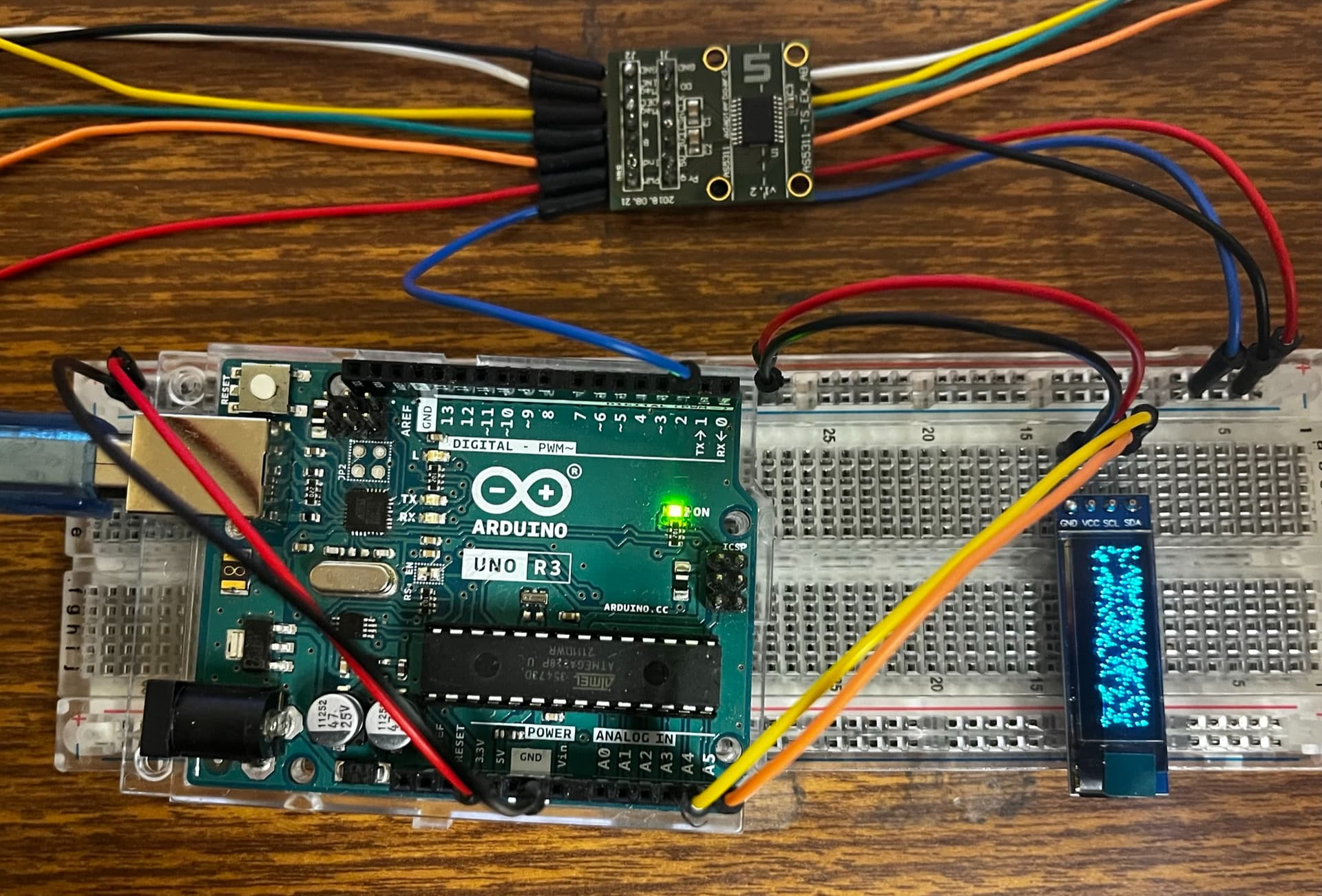
Any help and knowledge is appreciated. Thanks in advance.

Hello reevefernandes

Do not make display handling inside an ISR.

Have a nice day and enjoy coding in C++.

Thank you for the response.

Would making the display section its own function be a good idea and invoking it in the ISR be a good idea? OR is it, not a good approach?

The sketch provides a loop() function.
In this function a display function can be called event driven by the ISR.

Read this for the data exchange of ISR generated data:

1 Like

Making the display section a function is a good idea, but calling that function from the ISR is no better than what you have.

1 Like

Thank you for the heads up. I read a bit deeper into Inturrpts and ISR after your suggestion, I have a new approach to this problem to try and I will update you on how it goes; while at it, I would like to know what you think about this approach.

I will create a global variable that is accessible both to the ISR and the loop in which I will write code to display this variable. Every time the IRS is invoked it will give me a new number and I can use that to be displayed on the OLED screen.

The only downfall I see with this method is that the time the screen needs to do its thing before it starts putting stuff on the screen is much much longer than how often the interrupts fire, and I fear that maybe the screen has enough time ever to make the change.

I will drop in the code to implement the changes shortly. Kindly let me know what you think about the same and how would I combat this possible pitfall.

Thanks in advance!

I tried this method and it seemed to work just fine! I declared the variables as global volatiles at the top and it seemed to share data outside the IRS properly.

Here's the code

// Include Wire Library for I2C connection
#include <Wire.h>

// Include Adafruit Graphics & OLED libraries
#include <Adafruit_GFX.h>
#include <Adafruit_SSD1306.h>

// Reset pin not used but needed for Library
#define OLED_RESET 4
Adafruit_SSD1306 display(OLED_RESET);

// Declaring variables: interrupts need volatile variables
volatile float pwm_value = 0;
volatile float prev_time = 0;
volatile float result;

void setup() {

  // Testing purposes only
  Serial.begin(115200);

  // Start Wire library for I2C
  Wire.begin();

  // Initialize OLED with I2C add 0x3C
  display.begin(SSD1306_SWITCHCAPVCC, 0x3C);

  // The screen needs a couple of seconds after initialization to get going.
  delay(2000);

  // Attach interrupt for PMW. 
  // Interrupts in computer programming are events that temporarily pause 
  // the execution of a program to handle a specific task or event that 
  // requires immediate attention. They are commonly used in operating 
  // systems, device drivers, and embedded systems to handle input and 
  // output operations and manage system resources.

  // In the event there is a rising edge (represented by the last
  // argument in the function) on pin D2 (represented by 0
  // as the first argument), the attached interrupt will break from 
  // normal code flow and execute the interrupt service routine (ISR)
  // which is a function called in the second argument
  attachInterrupt(0, rising, RISING);

}

void loop() {

  // The loop continuously prints the result variable from the falling
  // function, along with the supporting text:
  // This is what you'll see on your OLED;
  // Linear Sensor
  // x: 0.000000 mm

  display.clearDisplay();
  display.setTextColor(WHITE);
  display.setTextSize(1);
  display.setCursor(0, 0);
  display.print("Linear Sensor");
  display.setCursor(0, 15);
  display.setTextSize(1.5);
  display.print("x: ");
  display.setTextSize(1);
  display.setCursor(15,15);
  display.print(result,6);
  display.setCursor(65, 15);
  display.print("mm");
  display.display();

 }


void rising() {
  // This function is called when the linear sensor
  // sends a high pulse (raising edge of PWM) into 
  // pin D2 saves the timestamp of the raising edge

  // Also attaches another interrupt to catch the falling
  // edge of the PWM and routes to the falling function
  attachInterrupt(0, falling, FALLING);
  prev_time = micros();
}

void falling() {
  // This function takes another timestamp and subtracts the
  // previous timestamp to find the time interval of PWM

  detachInterrupt(0);
  pwm_value = micros()-prev_time;
  //Acording to the documentation: 0 us = 0 mm; 4096us = 2mm
  result = pwm_value*2/4095;
  attachInterrupt(0, rising, RISING);
}

Edit:
Here is a link to the short demonstration of the final project Magnetic Linear Sensor with Arduino and OLED Display Demonstration - YouTube

Thanks for all the help!

This topic was automatically closed 180 days after the last reply. New replies are no longer allowed.