I tried to make a code as below:
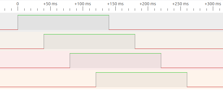
I have four I2C channels. The timing gap of starting time (or activation time) between each channel will be 40ms. Also, the activation time of each channel will be 140ms. Here is the figure to run.
What are these devices? Perhaps describing your project woukd help me make any sense of your timing diagram.
Yes, maybe it could be reverse engineered from your code, sorry, too old to spend time on that!
Maybe you should focus on separate issues.
get four things to happen on your time schedule
That could be printing or illuminating separate LEDs. You could vastly slow down the time scale until you had reliable mechanism for doing things on time in order.
come to grips with how the I2C multiplexer works
To be sure you are able to talk with a particular device from all them, perhaps determined by an index variable, just an int 0 or 1 or whatever to say which.
1 + 2 = 3. Fix the timing back to rapid, throw in your ability to talk to the device you want at will and…
you'll be done.
It will be easier to help you with each of the two totally separate aspects of the entire goal.
I am confused. When you ran the code, did it do what you wanted it to do? If so, it's likely the right code. If it didn't do what you wanted, then how did it fail?
I think that you want to solve something that does not exist.
When we get a question like this, then it is often a XY problem: https://xyproblem.info/
What do you want to achieve with that timeout on the I2C bus ?
The DRV2605L haptic controller has only one I2C address, so you need indeed a multiplexer.
The TCA9548A chip is a good I2C multiplexer.
If you want to control one of the haptic controllers, then you set the mux and send commands to that controller. How long the mux is activated does not matter.
If you want to disable all the I2C channels when not using the I2C bus, then you can do that directly after using one of the controllers.
The I2C bus is blocking, when a function of the Mux library returns, then the I2C session has completely finished and there is not need to keep the I2C active for something.
If you can provide illuminating separate LEDs with a specific duration time (Here 140ms) and time gap (Here 40ms) between the starting (on-time) of each LED, would you like to provide it? 140ms later after it illuminates, it will turn off also.
Do you want to control both the haptic controllers and leds ? That is no problem, but please do not try to make the I2C bus active or not, just use the I2C bus when needed.
I am a little bit confused about whether it is the right code as I described.
If I change the channelInterval variable small enough or as 0 , it should be perceived as simultaneous activation. But it still has some time gap between each channel.
Hopefully, I want to control four haptic controllers. I also have I2C multiplexer which I have used and written in my code.
My project is that I want to activate four vibration motors that are driven by the haptic driver. There should have specific time gap between each vibration activation starting time and each vibration will vibrate for specific duration time.
It is preferred to help you get something you've written to work.
But if I were to, I would need to see the diagram extended to show what happens and how the cyclic nature and staggered timing works out over a few cycles.
Or at least one and a half complete cycles.
What makes the cycles start and stop? Once initiated should we get one cycle that produces all four vibrations, or should the cycle repeat until it is told to stop?
If a repeating cyclic vibration pattern is being done, should stopping it just stop it no matter where in the pattern you are, or might you want to stop later, possibly, after the four part ps were all done?
If you don't answer these questions for us and yourself before you code anything, you will get the accidental answers that the code will provide for you when it runs…
Once one vibration activates, it will stop 140ms later after it activates. Moreover, 40ms later after the first vibration activates, 2nd vibration will activate. Then, 1->2->3->4 will activate sequentially with a time gap of 40 ms. Then, if last vibration activates for 140ms, the sequential activation (from 1 to 4) will be stopped. Does it make sense?
Sry the time line is not well scaled. If it looks like I drew that with my finger sitting under an umbrella at the beach with a half-empty cold one next to me, there's a reason for that.
// Timing of 4 things, starting 40ms after each other, staying active 140ms.
//
// Forum: https://forum.arduino.cc/t/asking-questions-for-i2c-channel-communication/1186203/16
// This Wokwi project: https://wokwi.com/projects/380693069509691393
//
// I can think of 4 good solutions.
// This is with delays.
// The code will do that sequence at the press of a button.

const int buttonPin = 2;

void setup()
{
  pinMode(buttonPin, INPUT_PULLUP);
  pinMode(4, OUTPUT);
  pinMode(5, OUTPUT);
  pinMode(6, OUTPUT);
  pinMode(7, OUTPUT);
}

void loop()
{
  int button = digitalRead(buttonPin);
  if(button == LOW)
  {
    digitalWrite(4, HIGH);
    delay(40);
    digitalWrite(5, HIGH);
    delay(40);
    digitalWrite(6, HIGH);
    delay(40);
    digitalWrite(7, HIGH);
    delay(20);
    digitalWrite(4, LOW);
    delay(40);
    digitalWrite(5, LOW);
    delay(40);
    digitalWrite(6, LOW);
    delay(40);
    digitalWrite(7, LOW);
  }
}