Assistance with code- Added functionality, lost basic function

Hi all- first time post, and I'm pretty new to Ardunio programming. I've got a few successful projects under my belt, but this one is getting the best of me!
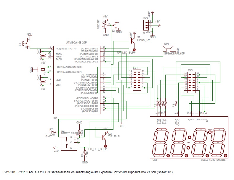
My project is to build a dual-sided PCB exposure box with Arduino controlled timer. I can get that working no problem.
I wanted to incorporate a door safety switch that, when open, turns off the UV, pauses the timer, and turns on a red LED array controlled by PWM set by a pot read by the arduino.
I wrote separate sketches that independently work, but when I combine them:

  1. Door switch input appropriately controls the red LED signal, and when open, shuts off the time circuit and UV Transistor. YAY.
  2. When door switch is closed, time circuit activates, red LED circuit turns off, BUT UV LED transistor is on.
  3. When door swtich is closed, I can set and/or activate countdown timer, and the timer functions, but UV LED transistor is on the whole time, regardless of button state or timer state.
  4. When I open the door switch mid cycle, the timer circuit pauses and shuts off (desired behavior) as does the UV transistor. When I close the door switch again, no matter how long, the timer picks up where it left off, the red LED goes off, and the UV LED turns on, but it stays on past timer expiration.

Somehow, by incorporating the door switch/LED code, I broke something..but I can't find it!

Here is the first version of the code- v12, that operates the timer setting, UV circuit and countdown just fine, but does not include the door switch, red LED and timer pause functionality. Following this will be a new post with the version I have (v14) that merges the switch, red LED and timer pause, but is not working:

/* This code works for setting, running time, and activating the UV array
when timer starts, and turns it off when the timer is up.  Still missing/not working:
Red light - PWM driven from POT connected to door switch
Door switch - turns off UV, turns on Red, and pauses timer
After cycle is finished, pushing the encoder resets timer, but turns UV on.
*/
#include <EEPROM.h>

int segmentPins[] = {12, 2, 13, 16, 18, 4, 5}; 
int displayPins[] = {6,15,7,14};
int times[] = {5, 10, 15, 20, 25, 30, 35, 40, 45, 50, 55, 100, 105, 110, 115, 120, 125, 130, 135, 140, 145, 150, 155, 200, 205, 210, 215, 220, 225, 230, 235, 240, 245, 250, 255, 300, 315, 330, 345, 400, 415, 430, 445, 500, 600, 700, 800, 900, 1000, 1500, 2000, 3000};
int numTimes = 52;
byte selectedTimeIndex;
int timerMinute;
int timerSecond;
int ledState = 10;
unsigned long previousMillis = 0;
const long interval = 500; //colonPin blink interval
int redPin = 3;
int transistorPin = 1;
int doorSwitch = A5;
int redIntensity = 0;


int colonPin = 11;
int aPin = 10;
int bPin = 8;
int buttonPin = 9;

boolean stopped = true;


byte digits[10][7] = {
//  a  b  c  d  e  f  g  
  { 1, 1, 1, 1, 1, 1, 0},  // 0
  { 0, 1, 1, 0, 0, 0, 0},  // 1
  { 1, 1, 0, 1, 1, 0, 1},  // 2
  { 1, 1, 1, 1, 0, 0, 1},  // 3
  { 0, 1, 1, 0, 0, 1, 1},  // 4
  { 1, 0, 1, 1, 0, 1, 1},  // 5
  { 1, 0, 1, 1, 1, 1, 1},  // 6
  { 1, 1, 1, 0, 0, 0, 0},  // 7
  { 1, 1, 1, 1, 1, 1, 1},  // 8  
  { 1, 1, 1, 1, 0, 1, 1}  // 9  
};
   
void setup()
{
  for (int i=0; i < 7; i++)
  {
    pinMode(segmentPins[i], OUTPUT);
  }
  for (int i=0; i < 4; i++)
  {
    pinMode(displayPins[i], OUTPUT);
  }
  pinMode(colonPin, OUTPUT);
  pinMode(buttonPin, INPUT);
  pinMode(aPin, INPUT);  
  pinMode(bPin, INPUT);
  pinMode(redPin, OUTPUT);
  pinMode(transistorPin, OUTPUT);
  pinMode(doorSwitch,INPUT);
  digitalWrite(transistorPin, LOW);
  
  
  selectedTimeIndex = EEPROM.read(0);
  timerMinute = times[selectedTimeIndex] / 100;
  timerSecond = times[selectedTimeIndex] % 100;
}

void loop()
{
  {
 if (digitalRead(buttonPin))

  {
    stopped = ! stopped;
    analogWrite(colonPin, ledState); 
    while (digitalRead(buttonPin)) {};
    EEPROM.write(0, selectedTimeIndex);
    digitalWrite(transistorPin,HIGH);
    
  }
  updateDisplay();
}
}
void updateDisplay() // mmss
{
  int minsecs = timerMinute * 100 + timerSecond;
  int v = minsecs;
  for (int i = 0; i < 4; i ++)
  {
      int digit = v % 10;
      setDigit(i);
      setSegments(digit);
      v = v / 10;
      process();
  }
  setDigit(5); // all digits off to prevent uneven illumination
}

void process()
{
  for (int i = 0; i < 100; i++) // tweak this number between flicker and blur
  {
    int change = getEncoderTurn();
    if (stopped)
    {
      changeSetTime(change);
    }
    else
    {
      updateCountingTime();
    }
  }
  if (timerMinute == 0 && timerSecond == 0)
  {
    analogWrite(colonPin,10);
    digitalWrite(transistorPin,LOW);
      }
     }


void changeSetTime(int change)
{
   selectedTimeIndex += change;
   if (selectedTimeIndex < 0)
   {
     selectedTimeIndex = numTimes;
   }
   else if (selectedTimeIndex > numTimes)
   {
     selectedTimeIndex = 0;
   }
   timerMinute = times[selectedTimeIndex] / 100;
   timerSecond = times[selectedTimeIndex] % 100;
}

void updateCountingTime()
{
   static unsigned long lastMillis;
   unsigned long m = millis();
   if (m > (lastMillis + 1000) && (timerSecond > 0 || timerMinute > 0))
   {
    
    unsigned long currentMillis = millis();
    if (currentMillis - previousMillis >= interval) {
      previousMillis = currentMillis;
      // if LED is off, turn it on, and vice-versa
      if (ledState == 0){
        ledState = 10;
      }else {
        ledState = 0;
      }
      analogWrite(colonPin, ledState); 

    if (timerSecond == 0)
    { 
       timerSecond = 59;
       timerMinute --;
    }
    else
    {
       timerSecond --; 
    }
    lastMillis = m;
  }
}
}
void setDigit(int digit)
{
  for (int i = 0; i < 4; i++)
  {
    digitalWrite(displayPins[i], (digit == i));
  } 
}

void setSegments(int n)
{
  for (int i = 0; i < 8; i++)
  {
    digitalWrite(segmentPins[i],! digits[n][i]);
  } 
}


int getEncoderTurn()
{
  // return -1, 0, or +1
  static int oldA = LOW;
  static int oldB = LOW;
  int result = 0;
  int newA = digitalRead(aPin);
  int newB = digitalRead(bPin);
  if (newA != oldA || newB != oldB)
  {
    // something has changed
    if (oldA == LOW && newA == HIGH)
    {
      result = -(oldB * 2 - 1);
    }
  }
  oldA = newA;
  oldB = newB;
  return result;
}

and here is the "broken" code- I tried to compare line by line, and I see what I added, but I don't see why it's not working with the UV transistor (pin 1).

Here is v14: Same as above, with the working bits of v13 (door switch sense, red LED on/PWM control, timer pause) integrated:

/* This code activates the timer circuit when the door is closed, allows for the time 
 *  interval to be set, but the whole time the door is closed, the UV circuit (pin1) is on
 *  This never turns off, even when the timer expires.  Only time it goes off is if door
 *  switch is opened, which it should, but it shouldn't go on until the timer starts.
*/
#include <EEPROM.h>

int segmentPins[] = {12, 2, 13, 16, 18, 4, 5}; 
int displayPins[] = {6,15,7,14};
int times[] = {5, 10, 15, 20, 25, 30, 35, 40, 45, 50, 55, 100, 105, 110, 115, 120, 125, 130, 135, 140, 145, 150, 155, 200, 205, 210, 215, 220, 225, 230, 235, 240, 245, 250, 255, 300, 315, 330, 345, 400, 415, 430, 445, 500, 600, 700, 800, 900, 1000, 1500, 2000, 3000};
int numTimes = 52;
byte selectedTimeIndex;
int timerMinute;
int timerSecond;
int ledState = 10;
unsigned long previousMillis = 0;
const long interval = 500; //colonPin blink interval
int redPin = 3;
int transistorPin = 1;
int doorSwitch = A5;
int redIntensity = 0;


int colonPin = 11;
int aPin = 10;
int bPin = 8;
int buttonPin = 9;

boolean stopped = true;


byte digits[10][7] = {
//  a  b  c  d  e  f  g  
  { 1, 1, 1, 1, 1, 1, 0},  // 0
  { 0, 1, 1, 0, 0, 0, 0},  // 1
  { 1, 1, 0, 1, 1, 0, 1},  // 2
  { 1, 1, 1, 1, 0, 0, 1},  // 3
  { 0, 1, 1, 0, 0, 1, 1},  // 4
  { 1, 0, 1, 1, 0, 1, 1},  // 5
  { 1, 0, 1, 1, 1, 1, 1},  // 6
  { 1, 1, 1, 0, 0, 0, 0},  // 7
  { 1, 1, 1, 1, 1, 1, 1},  // 8  
  { 1, 1, 1, 1, 0, 1, 1}  // 9  
};
   
void setup()
{
  for (int i=0; i < 7; i++)
  {
    pinMode(segmentPins[i], OUTPUT);
  }
  for (int i=0; i < 4; i++)
  {
    pinMode(displayPins[i], OUTPUT);
  }
  pinMode(colonPin, OUTPUT);
  pinMode(buttonPin, INPUT);
  pinMode(aPin, INPUT);  
  pinMode(bPin, INPUT);
  pinMode(redPin, OUTPUT);
  pinMode(transistorPin, OUTPUT);
  pinMode(doorSwitch,INPUT);
  digitalWrite(transistorPin, LOW);
  
  
  selectedTimeIndex = EEPROM.read(0);
  timerMinute = times[selectedTimeIndex] / 100;
  timerSecond = times[selectedTimeIndex] % 100;
}

void loop()
{
  redIntensity = analogRead(doorSwitch);
  redIntensity = map(redIntensity, 0, 1023, 0, 255);
  analogWrite(redPin, redIntensity);
  while(digitalRead(doorSwitch))
  {
   digitalWrite(transistorPin, LOW);
 
    
  }
  {
 if (digitalRead(buttonPin))

  {
    stopped = ! stopped;
    digitalWrite(transistorPin,HIGH);
    analogWrite(colonPin, ledState); 
    while (digitalRead(buttonPin)) {};
    EEPROM.write(0, selectedTimeIndex);
    
    
  }
  
  updateDisplay();
  digitalWrite(transistorPin,LOW);

}
}
void updateDisplay() // mmss
{
  int minsecs = timerMinute * 100 + timerSecond;
  int v = minsecs;
  for (int i = 0; i < 4; i ++)
  {
      int digit = v % 10;
      setDigit(i);
      setSegments(digit);
      v = v / 10;
      process();
  }
  setDigit(5); // all digits off to prevent uneven illumination
}

void process()
{
  for (int i = 0; i < 100; i++) // tweak this number between flicker and blur
  {
    int change = getEncoderTurn();
    if (stopped)
    {
      changeSetTime(change);
    }
    else
    {
      updateCountingTime();
    }
  }
  if (timerMinute == 0 && timerSecond == 0)
  {
    analogWrite(colonPin,10);
    digitalWrite(transistorPin,LOW);
      }
     }


void changeSetTime(int change)
{
   selectedTimeIndex += change;
   if (selectedTimeIndex < 0)
   {
     selectedTimeIndex = numTimes;
   }
   else if (selectedTimeIndex > numTimes)
   {
     selectedTimeIndex = 0;
   }
   timerMinute = times[selectedTimeIndex] / 100;
   timerSecond = times[selectedTimeIndex] % 100;
}

void updateCountingTime()
{
   static unsigned long lastMillis;
   unsigned long m = millis();
   if (m > (lastMillis + 1000) && (timerSecond > 0 || timerMinute > 0))
   {
    
    unsigned long currentMillis = millis();
    if (currentMillis - previousMillis >= interval) {
      previousMillis = currentMillis;
      // if LED is off, turn it on, and vice-versa
      if (ledState == 0){
        ledState = 10;
      }else {
        ledState = 0;
      }
      analogWrite(colonPin, ledState); 

    if (timerSecond == 0)
    { 
       timerSecond = 59;
       timerMinute --;
    }
    else
    {
       timerSecond --; 
    }
    lastMillis = m;
  }
}
}
void setDigit(int digit)
{
  for (int i = 0; i < 4; i++)
  {
    digitalWrite(displayPins[i], (digit == i));
  } 
}

void setSegments(int n)
{
  for (int i = 0; i < 8; i++)
  {
    digitalWrite(segmentPins[i],! digits[n][i]);
  } 
}


int getEncoderTurn()
{
  // return -1, 0, or +1
  static int oldA = LOW;
  static int oldB = LOW;
  int result = 0;
  int newA = digitalRead(aPin);
  int newB = digitalRead(bPin);
  if (newA != oldA || newB != oldB)
  {
    // something has changed
    if (oldA == LOW && newA == HIGH)
    {
      result = -(oldB * 2 - 1);
    }
  }
  oldA = newA;
  oldB = newB;
  return result;
}

Please help!

Thanks!!

Dave

To compare versions I find that notepad++ with the 'compare' plugin (load from the plugins->plugin manager) gives a nice side-by-side display with color-coded differences.

Your second version appears to have (in loop())

   updateDisplay();
   digitalWrite(transistorPin,LOW)

Whereas the original has only updateDisplay()

not sure if this is the problem.

Also be careful of writing to EEPROM
The way you have it, the write will occur repeatedly when the button is pressed...
this may 'wear out' your EEPROM faster than you expect.

check for change of button state, and only act when it is 'pressed' or 'released' - as preferred.

Hi,

  1. When door switch is closed, time circuit activates, red LED circuit turns off, BUT UV LED transistor is on.

What UV LED transistor?
Can you please post a copy of your circuit, in CAD or a picture of a hand drawn circuit in jpg, png?
A picture showing your project would also help.

Thanks Tom.... :slight_smile:

rw950431:
To compare versions I find that notepad++ with the 'compare' plugin (load from the plugins->plugin manager) gives a nice side-by-side display with color-coded differences.

Your second version appears to have (in loop())

   updateDisplay();

digitalWrite(transistorPin,LOW)


Whereas the original has only updateDisplay()

not sure if this is the problem.

I found that too, and you're right- that is a great tool! Unfortunately removing it, or swapping position of those two lines has no positive effect. Thank you for looking though!

lastchancename:
Also be careful of writing to EEPROM
The way you have it, the write will occur repeatedly when the button is pressed...
this may 'wear out' your EEPROM faster than you expect.

check for change of button state, and only act when it is 'pressed' or 'released' - as preferred.

Great advice! Thanks!

TomGeorge:
Hi,What UV LED transistor?
Can you please post a copy of your circuit, in CAD or a picture of a hand drawn circuit in jpg, png?
A picture showing your project would also help.

Thanks Tom.... :slight_smile:

:blush: of course that WOULD be helpful, sorry!! I will try to shoot a quick video of the breadboard running both sketches, video is worth a million words. Here's the schematic- Q1 is the offending bugger. I've ruled out hardware failure.

UV exposure box v1 sch.pdf (17.3 KB)

And here is a 2 min video of v12 followed by v14, if this helps!

Thank you!!

No PULLUP resistor on reset.
No series base resistors. Consider MOSFETs
No limiting speaker resistor.

Hi,
Thanks for the schematic, but we need to see all your other connections, what the transistor is connected too, what you are using and how you have power supplies connected.

Thanks.. Tom... :slight_smile:

TomGeorge:
Hi,
Thanks for the schematic, but we need to see all your other connections, what the transistor is connected too, what you are using and how you have power supplies connected.

Thanks.. Tom... :slight_smile:

Hi Tom- did you get a chance to watch the video I posted? Right now this is only in breadboard stage, and I'm not actually driving a transistor. I used that term because eventually, as shown in the schematic, I will be (and it's called transistorPin in the sketch). For testing, I'm only driving a single LED with a current limiting resistor. The entire bread board is driven right now from the arduino supply. When I get this figured out and make the board, it will have a 5vdc and a 24vdc input, as shown on the schematic.
The transistor will be 24vdc in, and will connect to two arrays of UV LED on off-board panels. Those are made, and work, but are not connected to the test bed. Thanks!!

LarryD:
No PULLUP resistor on reset.
No series base resistors. Consider MOSFETs
No limiting speaker resistor.

great catch on the reset, and I wasn't sure it would be necessary on the bases. I can add them in no problem, would protect the atmel chip for sure. Ditto for the beeper, thanks!!

Hi,

Tom... :slight_smile:

TomGeorge:
Hi,

Tom... :slight_smile:

I appreciate the personal attention, but I'm not sure what to take from this post? I'm really confident that my hardware is not at fault, since v12 works exactly as it should, just missing the additional features.

Hi,
The reason for posting our circit like that is some platforms cannot upload attachments.
circuit222a.jpg
This bit has me worried, what is the Q2 TIP120 connected to?
If it is a RED LED where is the current limit resistor?
Also Q1, please expand your circuit to include ALL your hardware?
It looks like you are common collector switching.
With different power supplies for the LEDs and only 5V for the basecontrol you should be using common emitter and base resistors.

Thanks.. Tom.. :slight_smile:

TomGeorge:
Hi,
The reason for posting our circit like that is some platforms cannot upload attachments.
circuit222a.jpg
This bit has me worried, what is the Q2 TIP120 connected to?
If it is a RED LED where is the current limit resistor?
Also Q1, please expand your circuit to include ALL your hardware?
It looks like you are common collector switching.
With different power supplies for the LEDs and only 5V for the basecontrol you should be using common emitter and base resistors.

Thanks.. Tom.. :slight_smile:

Ah, I see- thanks for taking the time to do it correctly for me! I think the confusion comes from the fact that in my physical breadboard I'm not actually switching any transistors. I'm trying to work out the kinks in my code, so I have the transistors in the schematic replaced with current-limited LEDs on my breadboard. This is just to let me see the state of the pins. The schematic is accurate aside from that (well, I now will include resistors for my bases, and for the beeper (called speaker)); I plan to etch a PCB once I am certain the code is correct, which is what I need the assistance with now; it's not behaving the way I want. My current set up is 2 840point breadboards, and an Arduino Uno- As you can see in the schematic, my plan is to flash the atmel, and run it on the board.

I hate to keep asking this, but have you viewed the video? I think that will make all of this more clear.

To address your other questions, my power supply is a +5, +24 with common ground. The +5v is for the microcontroller and probably the red LED array (as of yet just an idea, I've only built the UV panels). The TIP120 in the schematic may be replaced with MOSFET or something more modern, they are there simply so I can get pads on the board, and show that there are off-board connections (the missing hardware: two UV LED array panels, driven by 24v, and the previously mentioned (and much smaller) red array).

PS- the LED outputs of Q1 and Q2 don't show the current limiting resistors because they are part of the array. That test point is simply for the panels to connect to.

Hi,
Do you have a flag or variable that indicates if the timer is ON or OFF?
You already have the timer doing the right things when the time counts down and or the door is open or closed.
If so then when you turn the timer on or off/pause you include a digitalWrite LOW or HIGH for the UV output, apart from the end of your setup to initialize the output.
I think its the "transistorpin" that is the UV lamp control, if so change its name to UVLamp, its more indicative of what that output pins does.

"redpin" ????is that the backlight? call it backlight please.

Sorry but I was put off by the read ability of your code, you are talking about UV and backlight control and timer start/stop yet you code has no reference to these names.
Sorry for the criticism but readability is important to allow others to help debug.

Tom..... :slight_smile:

TomGeorge:
Hi,
Do you have a flag or variable that indicates if the timer is ON or OFF?
You already have the timer doing the right things when the time counts down and or the door is open or closed.
If so then when you turn the timer on or off/pause you include a digitalWrite LOW or HIGH for the UV output, apart from the end of your setup to initialize the output.
I think its the "transistorpin" that is the UV lamp control, if so change its name to UVLamp, its more indicative of what that output pins does.

"redpin" ????is that the backlight? call it backlight please.

Sorry but I was put off by the read ability of your code, you are talking about UV and backlight control and timer start/stop yet you code has no reference to these names.
Sorry for the criticism but readability is important to allow others to help debug.

Tom..... :slight_smile:

Totally get it, great advice! I work in pathology, this is just something that fascinates me and I have no formal training. Should I go back and fix it and repost, or do you have a sense of what's going on now? Sorry it took 15 posts to get there.

"stopped" is the variable that drives the timer.

I think the bug is in this area:

void loop()
{
  redIntensity = analogRead(doorSwitch);
  redIntensity = map(redIntensity, 0, 1023, 0, 255);
  analogWrite(redPin, redIntensity);
  while(digitalRead(doorSwitch))
  {
   digitalWrite(transistorPin, LOW);
 
    
  }

The state of transistorPin is being controlled only by the state of doorSwitch, and not the code further down that controls the timer (and should drive the output of the transistorPin).

This block of code is next, and is the same between v12 (working) and v14 (not):

if (digitalRead(buttonPin))

  {
    stopped = ! stopped;
    analogWrite(colonPin, ledState); 
    while (digitalRead(buttonPin)) {};
    EEPROM.write(0, selectedTimeIndex);
    digitalWrite(transistorPin,HIGH);
    
    
  }

What I need is a better way of watching the input doorSwitch during the process, and setting "transistorPin" low, and "redPin" high, while pausing the timer when the doorSwitch input goes low.

Bumping this to see if anyone has any ideas on the post immediately above?