I'm working on a low-power project for which I'd like to use an ATMega328P using the 8MHz internal oscillator.
To this end, I've followed this[1] tutorial to burn an 8MHz bootloader to my (new) chip, using an old Duemilanove board as an ISP[2].
Once this is done I am able to upload to the chip successfully, but only once! The first upload goes fine, subsequent ones fail with:
avrdude: stk500_getsync() attempt 1 of 10: not in sync: resp=0x82
avrdude: stk500_getsync() attempt 2 of 10: not in sync: resp=0xc6
avrdude: stk500_getsync() attempt 3 of 10: not in sync: resp=0x87
avrdude: stk500_getsync() attempt 4 of 10: not in sync: resp=0x46
avrdude: stk500_getsync() attempt 5 of 10: not in sync: resp=0xe2
avrdude: stk500_getsync() attempt 6 of 10: not in sync: resp=0xa4
avrdude: stk500_getsync() attempt 7 of 10: not in sync: resp=0xa7
avrdude: stk500_getsync() attempt 8 of 10: not in sync: resp=0x86
avrdude: stk500_getsync() attempt 9 of 10: not in sync: resp=0x44
avrdude: stk500_getsync() attempt 10 of 10: not in sync: resp=0xf3
If I re-burn the bootloader to the chip I can upload again, but again only once
Can anyone give me some suggestions on where to start looking for the problem?
The "can only upload once" symptom is caused by a defective or absent auto-reset circuit.
In order to upload, the bootloader needs to be activated. This is done by resetting the microcontroller. However, the bootloader only runs for a short time before timing out and switching to running your sketch so the reset has to be timed just right during the upload. Normally, we have an auto-reset circuit set up that resets the microcontroller at just the right time during the upload. The auto reset circuit consists of the DTR or RTS on the USB to TTL serial adapter chip connected to the reset pin via a 0.1 uF capacitor. You can use either DTR or RTS, it doesn't matter which. In conjunction with the pull-up resistor (~10 kohm), this converts the signal on the DTR or RTS pin into a reset pulse at the right moment of the upload.
When you burn the bootloader, it erases the application section of the flash memory, which causes the bootloader to run constantly. This means the reset is not needed to activate the bootloader that first time you upload. But after that first upload, your sketch will be running and the upload can't succeed without the reset.
If you don't have an auto-reset circuit, you'll need to manually reset your Arduino during the upload. When you don't have that auto-reset, and are resetting manually, you need to get the timing right. If you press the reset button too early, the bootloader will have already timed out by the time the upload starts. The tricky thing is that when you press the "Upload" button in the Arduino IDE, it first compiles your sketch before starting the actual upload. So you need to wait until after the compilation finishes before pressing the reset button. The way to get the timing right is to watch the black console window at the bottom of the Arduino IDE window. As soon as you see something like this:
Sketch uses 444 bytes (1%) of program storage space. Maximum is 30720 bytes.
Global variables use 9 bytes (0%) of dynamic memory, leaving 2039 bytes for local variables. Maximum is 2048 bytes.
press and release the reset button (or use a wire to momentarily make the connection if you don't have a reset button attached). The upload should now finish successfully.
Your explanation makes perfect sense to me. I do have an auto-reset circuit as you describe, but since it's on a breadboard it's possible I misconnected something.
I tried some further investigation and am now confused (again).
I transfered my chip to a little board I built for doing ICSP bootloader burning. This is a board I've used previously for both ICSP and normal serial sketch upload, so I'm fairly confident of the auto-reset circuit and the connections to my USB to TTL serial adapter. I didn't want to use it previously for sketch upload since it has a 16MHz crystal and I wanted to prove out running and uploading without the crystal in place.
On this board:
with the normal 16MHz bootloader burned, I can upload sketches repeatedly with no issues;
with the 8MHz bootloader burned I can only upload once
I think that the fact the 16MHz bootloader allows me to upload repeatedly suggests that the auto-reset circuit is present and correct.
However! If I do the "manual reset" using a grounded wire and a steady hand, the 8MHz bootloader will indeed accept a sketch upload.
Is it possible the auto-reset circuit needs tweaking for use with 8MHz internal oscillator?
I noticed from the fuse descriptions of the ATMega that there's an option to disable the reset pin, and I confirmed that I've not accidentally somehow got that set
I then had a bit of a look at the auto-reset circuit.
Using an arduino (what else?) to make a very poor man's oscilloscope, I can see there is a blip on the reset line where the voltage does drop from 5v when the RTS line goes low on opening the serial port.
However, it seems to only get down to about ~3.1v or so, and the dip on the pin occurs over the course of about 16ms or so. I don't know whether that's sufficient to actually reset the chip (I can double check), but it's not clear in any case why the 8MHz and 16MHz bootloaders behave differently.
Given I'm measuring the above with a fairly hacky instrument it's maybe worth taking with a pinch of salt!
I took inspiration from this sketch[1] to make a faster-sampling arduino "oscilloscope" and used it to look in a bit more depth at the reset pin pulse on my board.
The ATMega328 datasheet[2] specifies that to trigger a reset, the reset pin must be pulled down to between 0.2 and 0.9 VCC for a minimum of 2.5us.
My chip's VCC is 5v, so the reset pin voltage range is 1v - 4.5v.
Based on the scope traces I was able to capture, the reset pin is being pulsed low by the above specification for something of the order of 3000us when the serial RTS line is driven low.
So in other words, I think my autoreset circuit is working as expected and per the datasheet specification, but it still fails to reboot an ATMega328 running an 8MHz bootloader.
At this point I'm thinking I'll either (a) program the 8MHz chip using ICSP, or I'll just give up and use a 16MHz bootloader for the project and live with the slightly higher power consumption
I'm really just posting this up in case anyone has any bright ideas, and for posterity!
Yes, it's exactly that, except (a) I don't have a reset button, and (b) I'm using RTS rather than DTR.
Check the 10K resistor and the 104 capacitor. Maybe try a 10uF capacitor just for a test.
Aye, been there done that!
I've tried to upload sketches using my little "burn a bootloader" board, and on a breadboard. The former has a 16Mhz crystal and facilities for ISCP but they're otherwise the same design - but of course different instances of 10k resistor and 104 capacitor.
I also experimented on the breadboard with using 10nF and 10uF capacitors, and I think 5k and 51k resistors to play with the RC network transient response but nothing seemed to stick.
It's strange since others are clearly running the 8Mhz bootloader with no problems, and the same reset circuit works fine with the same ATMega running the 16Mhz bootloader.
The only potentially weird thing is that my RTS on my USB/TTL board is 3.3 ish volts when it's high, and drops to 0 volts when the port is opened. The RX and TX lines are 5volts so I guess the USB board has some voltage boost for those. Not sure whether it should make any difference.
The reset pulse depends on the voltage drop on the RTS line. If RTS drops 3.3V because its only 3.3V when its high, then Reset is being pulled only to 5-3.3 = 1.7V through the capacitor when RTS goes to 0V, which may not be low enough. That said, as you point out, it works at 16MHz, so if it's the same RTS line, it should work.
If your UART's TX is 5V, then RTS and DTR should also be 5V. So if RTS is only 3.3V, it seems something may be wrong there. You haven't confused RTS with RST have you?
Which UART adapter are you using? Is it set to 5V?
Edit: I'm assuming you're powering the 328P at 5V. If that's correct, you might try powering it and the UART adapter at 3.3V, and see if it works then.
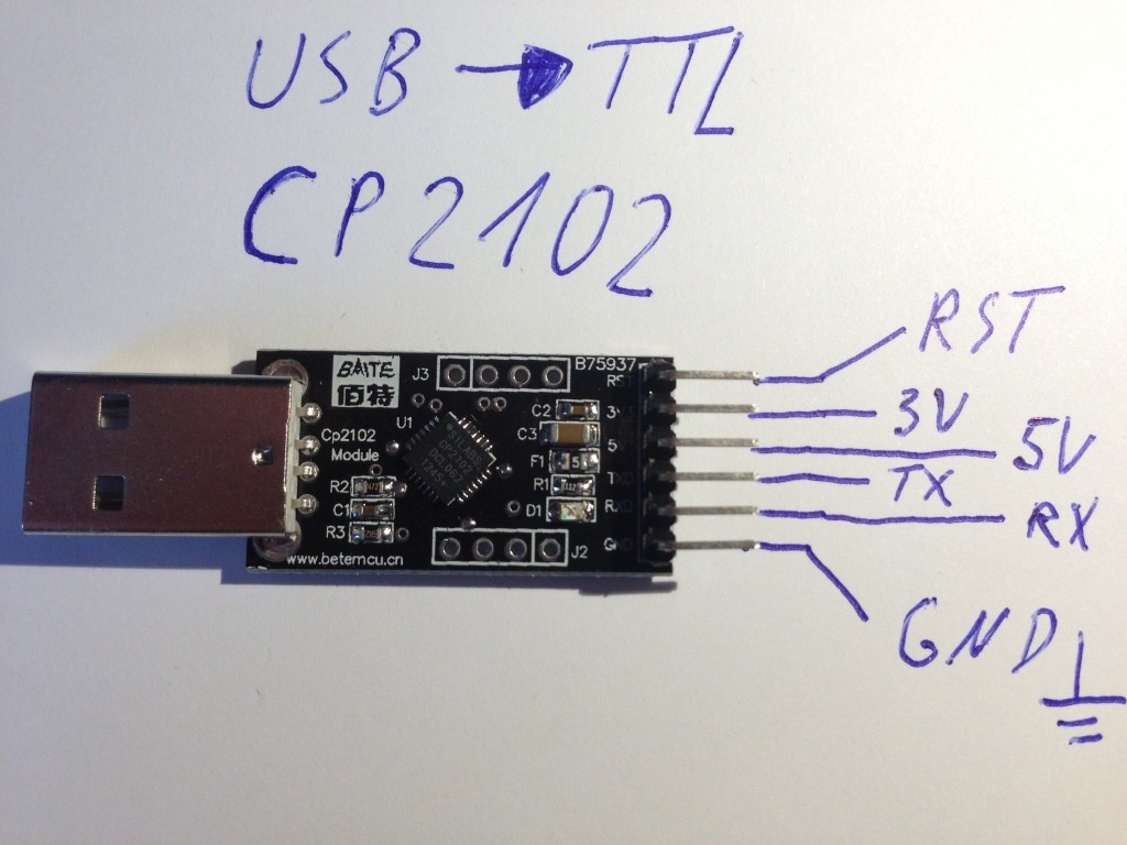
I'm using a little generic CP2102-based adapter from eBay, made by "Bate MCU"[1].
In terms of voltages, it supplies a "3.3v" (actually 3.5v according to my meter), and a "5v" (measures as 4.6v) supply. The serial TTL lines seem to operate in the 3.3v-ish domain. I had a quick look at the CP2102 datasheet and that adds up -- I guess my board provides access to the USB bus 5v as an option.
The reset pulse depends on the voltage drop on the RTS line. If RTS drops 3.3V because its only 3.3V when its high, then Reset is being pulled only to 5-3.3 = 1.7V through the capacitor when RTS goes to 0V, which may not be low enough...
Edit: I'm assuming you're powering the 328P at 5V. If that's correct, you might try powering it and the UART adapter at 3.3V, and see if it works then.
...and that turns out to be the answer. Power the 328P off the adapter 3.3v output and suddenly everything springs into life. Why it works for the 16MHz bootloader and not the 8MHz flavour I've no idea. The measured pulse looked sufficient to trigger a reset. But! The above is convincing enough for me
The CP2102 chip is a 3.3V device. So its Tx, RTS, and DTR should all be 3.3V. Apparently your module also feeds the USB 5V supply to an output header, presumably through a Schottky diode. But I think anything downstream of the CP2102 should be powered at 3.3V so everything will match. But I don't know why everything works at 5V with the 16MHz external crystal. It really shouldn't. Anyway, I'm glad it's working for you.
