I've created an schematic of an ATmega328P based development board, but i don't know if the board will work, so I was wondering if someone can tell me if it will work or if there are errors. Thanks in advance.

Is there a reason why you are designing such a development board rather than a board into which you can plug an Arduino such as a Nano
Yes, there's a reason: I'm designing it from nothing because i want to sell it on AliExpress.
That explains your other topic
To me, the Arduino IS a development board. Plus a programmer, plus it can be used as-is as a microcontroller board.

That's all? The other components and connections are good?
- Where did you discover the circuits you copied ?
From the internet, but I had to add a few things on my own. (ChatGPT gave me the auto selector, that is the shorted part) I only wanna know what are the wrong sections and their solutions.
-
Although drawing a schematic using net names is acceptable, it is not ideal, especially when first starting out or when asking people to review the work.
-
Highly suggest you avoid ChatGPT !
Why do you think that your board will be better than others, sell on Aliexpress already?
This is NOT good:

The diode should point the other way around. Now you've set it up to deliberately back-power the USB bus if external 5V is connected to the board.
![]()
Drawn confusingly, but technically OK. However, you're making it hard to spot flaws this way.
In general, in a schematic:
- Power is above the part, GND below it
- Signals go from left (input side) to right (output side)
- Avoid parts that overlap
- Avoid traces that cross if they're not connected
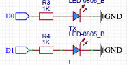
Your LEDs will be OFF when the TX/RX is ACTIVE. Maybe that's what you want, IDK. I generally do it the other way around.

Connect a diode with anode to RST and cathode to +5V to prevent a spurious spike due to discharge of a capacitor to force the ATMega into HV programming, erasing any sketch on it in the process (very annoying).
C8 is the same size as C4, which creates a problem with the RST pulse possibly not being 'LOW' enough when triggered through the CH340. Either leave out C8 or reduce it in size to e.g. 10nF.
![]()
This is incorrect. The cap needs to go between the V3 pin and GND, not to the 3.3V net. I do NOT recommend taking the 3.3V output from the CH340's regulator to the outside of the board since it's not intended to be a power supply. It can be used 'in a pinch' to power something very, very low-power, but breaking it out on an experimenter board invites all manner of problems ranging from peripherals not working as intended, to fried CH340's. We've seen this on the original Arduino Nano, and you may notice that Arduino has firmly left that practice behind them because of the trouble it caused. Just throw in an additional regulator. AMS1117 is popular, but a buck-mode DC-DC converter will also work and will be more efficient.
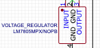
The 7805 is an ancient part. Better use something more modern with better performance; there are linear regulators with a much lower dropout voltage and better stability than the 7805. Personally I'd just use a buck mode DC-DC converter instead, which is overall much more efficient.

The 'VOUT' net doesn't appear to be going anywhere. Possibly ChatGPT played tricks on you. Mind also the remark about named nets by @LarryD above.
It's unclear what this part of the circuit is intended to do. On the original Arduino Nano, the diode which is U1 in your circuit acts as the 'auto selector' between BUS and VIN - that is to say, it prevents the board from trying to back-power VBUS (see first remark above). That's really all you need.
You don't have VOUT anywhere else on your board, so if you translate your present schematic to a PCB, it won't work if you connect 7V+ to VIN; the 7805 will feed into thin air and the rest of the board will be unpowered.
ChatGPT is not a substitute for understanding what you're doing. It often 'helps' by confusing people who (believe they) need it the most. Frankly, I don't think ChatGPT as any role in circuit design at this point in time.
There may be more flaws that I missed.
This is a pertinent question. The way it looks now, is that this board is basically a Nano clone (but with some major design flaws). Having some of these manufactured in China (e.g. JLCPCB) will result in each PCB without any components costing a few times more than a fully assembled, working Nano clone from China. So it's a more expensive, risky way to make something that's readily available for a low price. It doesn't make any sense.
This whole thread looks weird - a person who clearly has little understanding of electronics, decided to create a board with the help of AI that would compete in the market...
This could have had some chance if he had some original idea that would distinguish his board from others. But in the current thread such ideas are not visible.
It's a little odd, yes. I interpret it as a combination of:
1: "Making your own PCB looks kind of cool, but I'm not sure what to make, so let's re-create something that's already there"
2: "I'd like to learn to layout a PCB and it doesn't really matter what it does, as long as it does something"
3: "I could buy a Nano (clone), but I'd like to be able to say 'I made that' so instead I'll make my own clone."
What is your board's "USP" (Unique Selling Point)?
You will not be able to compete on price with the other Arduino clones already available, so you will need a compelling USP to achieve any sales.
None of these options suggest "I want to sell it on Ali"
Sorry, I missed that bit, you're right.
I don't see any sense in trying to sell this on Ali (or anywhere else). It can be useful as an educational exercise. Commercially, it's dead in the water.
When considering putting a new product on the market, ask yourself what problem it solves, and how it does this better than the competition. In this case, there's no good answer to either of these questions. The result is that you can anticipate a commercial failure.
I feel more sorry for the users who will buy this, because a board designed without understanding will inevitably contain errors.
Another one on Ali, of which there are already many
I thought that I was the only one who hates (images of) schematics that are like that. I really dislike it if I can't follow lines and I have to go all over the schematic to find where a certain pin is connected to (and possibly miss some of the connections).