I placed an ATMEGA328 TQFP on a PCB and set connections to bootload it and program it.
In order to bootload it, I used an arduino as the bootloader with no external crystal via this tutorial here: http://www.bashmodulo.com/arduino/burn-arduino-atmega-bootloader/
I downloaded Arduino 0022 to do this, as I had issues with editing the board.txt file in the Arduino 1.5.8 directory.
Bootload was successful, and the next step was to program it using an FTDI adapter, which I did via this tutorial here:
This was also successful as I was able to upload a simple blinky program to it. But now my issue arises when I try to switch to power the ATMEGA at 3.3v. It does not turn on and operate the blinky program. But it always turns back on when I power it with 5v.
Why is this? Is the voltage you program the chip at the same voltage needed to power it? Does it have something to do with bootloading it at a certain voltage?
How can I set this up such that I can run the circuit at 3.3v? I need to do so instead of 5v as I utilize a sensor device that runs at 3.3v.
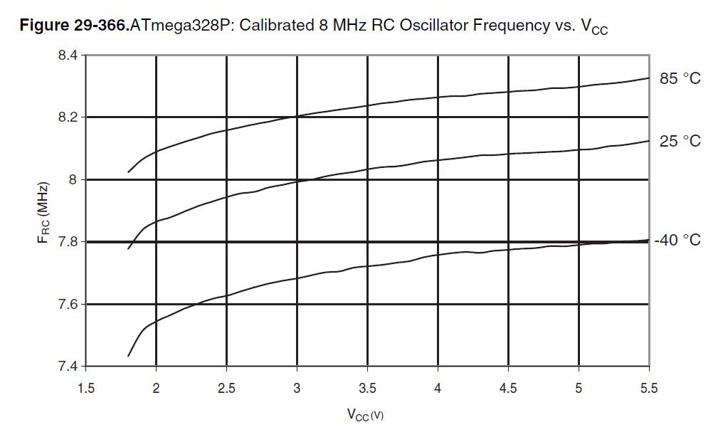
The frequency of internal "8MHz" oscillator varies with the voltage. It is set by manufacturer to 8MHz at 3.0V.
So the clock frequencies at 3.3V or 5.0V will be different.
The blink shall work at both voltages, what could be an issue is the Serial, which reliability depends on the proper clock frequency. So the serial upload may not work.
What is your upload serial speed there?
Is your chip a 328 or a 328p ??
I had the same problem recently and almost made a post on here about it. Turned out my problem was the 3.3V output from my USBasp. It worked fine at 5V and at 3.3V it would program it but woulsnt run properly. Switching to battery supply of 2.8V and it worked fine.
pito:
The frequency of internal "8MHz" oscillator varies with the voltage. It is set by manufacturer to 8MHz at 3.0V.
So the clock frequencies at 3.3V or 5.0V will be different.
The blink shall work at both voltages, what could be an issue is the Serial, which reliability depends on the proper clock frequency. So the serial upload may not work.
What is your upload serial speed there?
Is your chip a 328 or a 328p ??
Turned out I was only providing +3.3v to pin 7 on the 328, not pins 7 and 20.
duh@me
Funnily enough it works fine from 3.3v on just pin 20.
On a related note, it appears any remotely recent version of the arduino ide doesn't have correct fuse settings for the internal 8mhz oscillator under lilypad and such. Nick Gammon has a page discussing using bare chips at
and wrote several VERY useful sketches, one of which burns a working lilypad bootloader to a connected chip.
danielMRV:
I placed an ATMEGA328 TQFP on a PCB and set connections to bootload it and program it.
In order to bootload it, I used an arduino as the bootloader with no external crystal via this tutorial here: http://www.bashmodulo.com/arduino/burn-arduino-atmega-bootloader/
I downloaded Arduino 0022 to do this, as I had issues with editing the board.txt file in the Arduino 1.5.8 directory.
This was also successful as I was able to upload a simple blinky program to it. But now my issue arises when I try to switch to power the ATMEGA at 3.3v. It does not turn on and operate the blinky program. But it always turns back on when I power it with 5v.
Why is this? Is the voltage you program the chip at the same voltage needed to power it? Does it have something to do with bootloading it at a certain voltage?
How can I set this up such that I can run the circuit at 3.3v? I need to do so instead of 5v as I utilize a sensor device that runs at 3.3v.
Try setting your oscillator to full swing mode (set bit 3 (CKSEL3) of the low fuse to 0). Typically, this is changing LFUSE from 0xFF to 0xF7. This will make your crystal oscillator a LOT more robust.
Edit: My post was not applicable. Noticed that the OP is using the internal oscillator.
rc31o5:
On a related note, it appears any remotely recent version of the arduino ide doesn't have correct fuse settings for the internal 8mhz oscillator under lilypad and such. Nick Gammon has a page discussing using bare chips at
You can use MCUDude's MiniCore for bare/custom '328p based projects - it has support for that.
krupski: Try setting your oscillator to full swing mode (set bit 3 (CKSEL3) of the low fuse to 0). Typically, this is changing LFUSE from 0xFF to 0xF7. This will make your crystal oscillator a LOT more robust.
Edit: My post was not applicable. Noticed that the OP is using the internal oscillator.
You realise that you replied to a post that is over 4 years old