Hello, I've been trying to familiarize myself with the 328P's sleep modes. In the course of trying to reduce the current consumption I ended up constructing a socketed test jig with all the MCU's I/O pins connected to ground via 100K resistors and 3 10-ohm resistors that feed power to the Vcc, AVcc, and Vref pins, respectably. I'm using a differential amplifier that I can connect across any 10-ohm resistor in order to view on an oscilloscope the current draw of the pin that it feeds. The amplifier has a gain of 10, so 1 mV on the scope should indicate a current of 10 µA.
The MCU is running from its internal 8-MHz oscillator with the DIV8 fuse set, for an operation frequency of 1 MHz.
My code has been reduced down to nothing more than setting up the MCU for minimal power consumption and then a loop that puts the MCU into power-down sleep, from which it gets woken by the watchdog timer every ~35 mS.
On the scope I can clearly see the wake-up cycles occurring, with the current on the Vcc pin going to just about 1 mA, which corresponds nicely to what the datasheet shows for active current at 5V and 1MHz (The current draw on the AVcc and VRref pins are below what I can detect, as expected). However, during sleep the Vcc current only drops to about 190 µA, when I'd expect it to be somewhere close to 7µA, as per the datasheet. This a a big difference!
I would greatly appreciate it if anyone could enlighten me as to what I'm overlooking.
Edit: I realized I should also mention that I'm using MCUdude's Minicore package.
Edit 2: The fuse settings are as follows:
Extended: 0xFF; High: 0xD1; Low: 0x42
CKDIV8: Yes
CKOUT: No
SUT1: Yes
SUT0: Yes
CKSEL3: Yes
CKSEL2: Yes
CKSEL1: No
CKSEL0: Yes
RSTDISBL: No
DWEN: No
SPIEN: Yes
WDTON: No
EESAVE: Yes
BOOTSZ1: Yes
BOOTSZ0: Yes
BOOTRST: No
BODLEVEL2: No
BODLEVEL1: No
BODLEVEL0: No
My code:
#include <avr/wdt.h>

void setup()
{

  wdt_disable();  // Disable Watchdog Timer
  MCUSR = 0;      // Clear reset flags

  noInterrupts();

  DDRB = 0;  // All PORTB pins are inputs and pulled down externally
  PORTB = 0;

  DDRC = 0;  // All PORTC pins (except PC6/~RESET) are inputs and pulled down externally
  PORTC = 0;

  DDRD = 0;  // All PORTD pins are inputs and pulled down externally
  PORTD = 0;

  // Disable Digital Input Buffers on ADC lines
  DIDR0 = (1 << ADC0D) |
          (1 << ADC1D) |
          (1 << ADC2D) |
          (1 << ADC3D) |
          (1 << ADC4D) |
          (1 << ADC5D);

  // Disable unused interrupts
  EIMSK = 0;   // External Interrupts
  PCICR = 0;   // Pin Change interrupts
  UCSR0B = 0;  // Serial interrupts
  TIMSK0 = 0;  // Timer0 interrupts
  TIMSK1 = 0;  // Timer1 interrupts
  TIMSK2 = 0;  // Timer2 interrupts
  SPCR = 0;    // SPI interrupt
  EECR &= ~(1 << EERIE);  // EEPROM Ready interrupt
  TWCR = 0;    // TWI interrupt

  ACSR = 0;  // Disable Analog Comparator
  ADCSRA = 0;  // Disable ADC

  TCCR0B = 0;  // Stop Timer0
  TCCR1B = 0;  // Stop Timer1
  TCCR2B = 0 ; // Stop Timer2

  PRR |=  (1 << PRTWI)    |    // Shut down TWI
          (1 << PRTIM2)   |    // Shut down Timer2
          (1 << PRTIM0)   |    // Shut down Timer0
          (1 << PRTIM1)   |    // Shut down Timer1
          (1 << PRSPI)    |    // Shut down SPI
          (1 << PRUSART0) |    // Shut down USART0
          (1 << PRADC) ;       // Shut down ADC

  wdt_enable(WDTO_30MS);  // Configure Watchdog Timer for 30 milliseconds
  WDTCSR |= (1 << WDIE);  // Put the WDT into Interrupt mode

  interrupts();

  for (;;)
  {
    set_sleep_mode(SLEEP_POWER_DOWN);
    sleep();
    set_sleep_mode(SLEEP_IDLE);
  }

}


void loop()
{
}


ISR(WDT_vect)
{
  WDTCSR |= (1 << WDIE);  // Put the WDT back into Interrupt mode
}
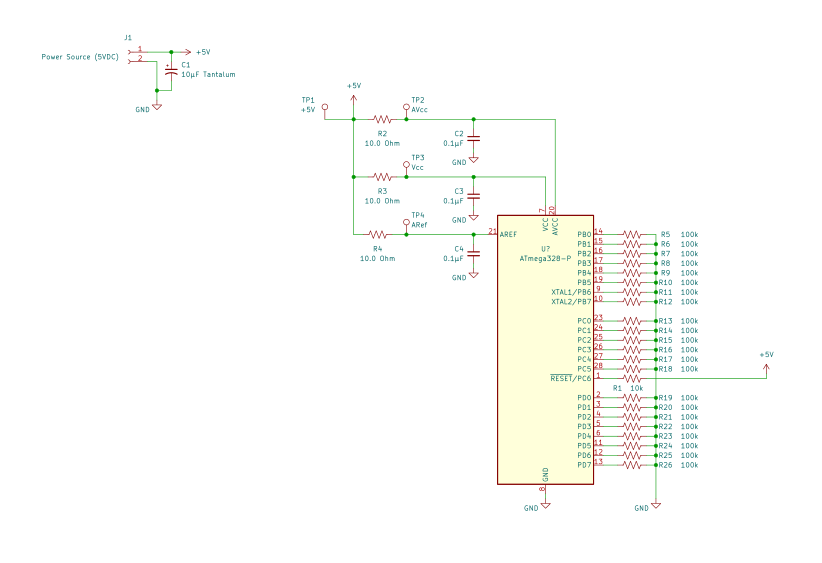
My circuit: