I'm having issues burning the bootloader on an Atmega328PB-AU. I'm using at Arduino Mega as ISP, with these options:
board:Arduino Duemilanove or Diecimila
Processor: Atmega328P
Programmer: Arduino as ISP.
The Atmega is embedded in a circuit, made by PCBway, so bad joints are not probable. You can see the relevant part of the schematic, I used an external clock source and I think I used caps everywhere I should. The jumper on the reset line is used for self reset in the software, it's left open for programming. On the Arduino, I used a 10uF cap between reset and GND.
When I try to burn the bootloader, I get this:
         System wide configuration file is "C:\Program Files (x86)\Arduino\hardware\tools\avr/etc/avrdude.conf"

         Using Port                    : COM3
         Using Programmer              : stk500v1
         Overriding Baud Rate          : 19200
         AVR Part                      : ATmega328P
         Chip Erase delay              : 9000 us
         PAGEL                         : PD7
         BS2                           : PC2
         RESET disposition             : dedicated
         RETRY pulse                   : SCK
         serial program mode           : yes
         parallel program mode         : yes
         Timeout                       : 200
         StabDelay                     : 100
         CmdexeDelay                   : 25
         SyncLoops                     : 32
         ByteDelay                     : 0
         PollIndex                     : 3
         PollValue                     : 0x53
         Memory Detail                 :

                                  Block Poll               Page                       Polled
           Memory Type Mode Delay Size  Indx Paged  Size   Size #Pages MinW  MaxW   ReadBack
           ----------- ---- ----- ----- ---- ------ ------ ---- ------ ----- ----- ---------
           eeprom        65    20     4    0 no       1024    4      0  3600  3600 0xff 0xff
           flash         65     6   128    0 yes     32768  128    256  4500  4500 0xff 0xff
           lfuse          0     0     0    0 no          1    0      0  4500  4500 0x00 0x00
           hfuse          0     0     0    0 no          1    0      0  4500  4500 0x00 0x00
           efuse          0     0     0    0 no          1    0      0  4500  4500 0x00 0x00
           lock           0     0     0    0 no          1    0      0  4500  4500 0x00 0x00
           calibration    0     0     0    0 no          1    0      0     0     0 0x00 0x00
           signature      0     0     0    0 no          3    0      0     0     0 0x00 0x00

         Programmer Type : STK500
         Description     : Atmel STK500 Version 1.x firmware
         Hardware Version: 2
         Firmware Version: 1.18
         Topcard         : Unknown
         Vtarget         : 0.0 V
         Varef           : 0.0 V
         Oscillator      : Off
         SCK period      : 0.1 us

avrdude: AVR device initialized and ready to accept instructions

Error while burning bootloader.
Reading | ################################################## | 100% 0.02s

avrdude: Device signature = 0xffff00
avrdude: Expected signature for ATmega328P is 1E 95 16
         Double check chip, or use -F to override this check.

avrdude done.  Thank you.
Sometimes the code is 0xff0000, sometimes 0x000000.
I used the old style wiring in the Arduino ISP sketch, so my wiring is this:
ARDUINO MEGA---- BOARD
13 ------------------ SCK
12 ------------------ MISO
11 ------------------ MOSI
10 ------------------ RESET (with 4,7k resistor to 5V to pull it high)
5v ------------------ VCC
GND ---------------- GND
I checked the 5V on other parts of the circuit, power should be good. I also tried two sets of cables, they seem to conduct when I check them with a DMM.
Notice that on Arduino MEGA, MISO, MOSI and SCK are on pins 50, 51 and 52, repectively. You should also check the ArduinoISP sketch, correct, recompile and upload it accordingly for Mega, if that is the case.
I always use target board as Genuino UNO for my Atmega328P-AU based boards.
BTW, 4.7K pullup resistor is better to be replaced with 10K, but that is not essential here.
nzl123:
Notice that on Arduino MEGA, MISO, MOSI and SCK are on pins 50, 51 and 52, repectively. You should also check the ArduinoISP sketch, correct, recompile and upload it accordingly for Mega, if that is the case.
I always use target board as Genuino UNO for my Atmega328P-AU based boards.
BTW, 4.7K pullup resistor is better to be replaced with 10K, but that is not essential here.
It shouldn't be a problem, i used the old_style_wiring option. But to be sure, I tried with the 50-52 pins, still get 0x000000 device signature error. I also tried the circuit's own 5V supply instead of Arduino's, no luck. Changing the 4.7k would be challenging, it's SMD. I built this circuit with Atmega328P-AU (note that this time it's a PB-AU) before, it worked with 4.7k.
CrossRoads:
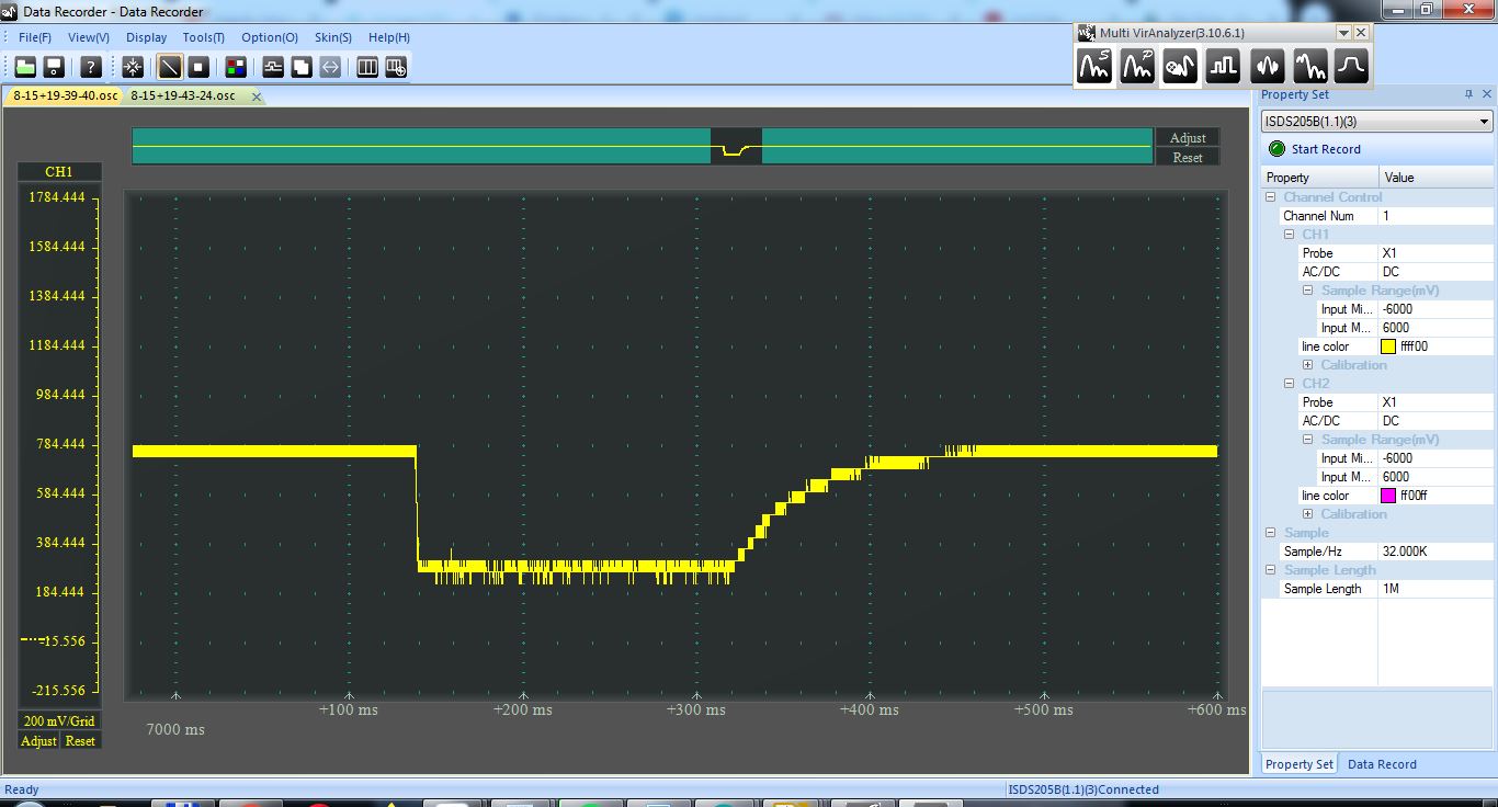
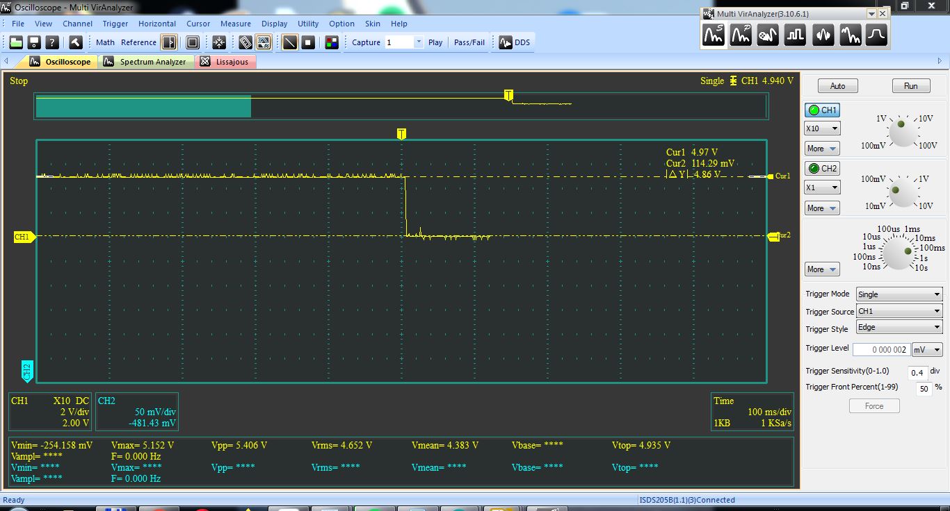
Can you get a scope trace on the Reset line? That 10uF might be keeping the Reset line up too long.
This is saying the chip is not responding properly:
avrdude: Device signature = 0xffff00
avrdude: Expected signature for ATmega328P is 1E 95 16
         Double check chip, or use -F to override this check.
Fuse bytes for ATmega328PB are 0x1E 0x95 0x16 so it is looking for a PB.
Here they are, I made a screenshot with a single trigger and cursors, but you can't see much after the trigger, so I also tried data recorder. I also made a shot without the external 10uF on the Arduino reset-GND lines (note that I have a 10uF and a 100nF to GND on the Atmega reset).
I did a config change in avrdude.conf from
part parent "m328"
    id = "m328p";
    desc = "ATmega328P";
    signature = 0x1e 0x95 0x0F;
to
part parent "m328"
    id = "m328p";
    desc = "ATmega328P";
    signature = 0x1e 0x95 0x16;
These are lines 8794-8797. But the main issue is not having a valid signature in the first place
balazs:
I used the old style wiring in the Arduino ISP sketch, so my wiring is this:
ARDUINO MEGA---- BOARD
13 ------------------ SCK
12 ------------------ MISO
11 ------------------ MOSI
10 ------------------ RESET (with 4,7k resistor to 5V to pull it high)
5v ------------------ VCC
GND ---------------- GND
I checked the 5V on other parts of the circuit, power should be good. I also tried two sets of cables, they seem to conduct when I check them with a DMM.
The schematic shows MISO0 on pin 23 and SCK0 on pin 24 which usually corresponds to SPI circuit 1.
Are you using SPI circuit 1 to program the chip? If so would you share how this is done?
The C112 and C115 will cause you troubles when trying to program using a FTDI232 USB-TTL after you have loaded the bootloader.
I don't see your connection for GND on Pin 21.
I have a feeling that you just spotted the cause of the error. PB3,PB4 and PB5 should be used for ISP, I used the wrong circuit for some reason. Fortunately, the right pins are left unconnected for future use, so I can wire them. Good catch. I will try it tomorrow.
Why will the caps cause trouble?
As for pin 21, Kicad have a habit of hiding some pins, but it is connected to GND.
When you use the USB-TTL circuit to upload sketches you need a 100nF capacitor in series with the DTR lead to give a reset pulse to the chip. With your combo of two capacitors to GND, the reset pulse will not make it to the chip.
One way around that is to have a Reset Switch and learn to time pressing it just as the sketch is ready to upload. Or just load using your ISP programmer after burning the fuses with the first bootloader upload.
kprims:
When you use the USB-TTL circuit to upload sketches you need a 100nF capacitor in series with the DTR lead to give a reset pulse to the chip. With your combo of two capacitors to GND, the reset pulse will not make it to the chip.
One way around that is to have a Reset Switch and learn to time pressing it just as the sketch is ready to upload. Or just load using your ISP programmer after burning the fuses with the first bootloader upload.
Thanks for your help. I tried the '0' pins for programming and now it works. I will stick with that for now.