ATtiny interrupt problem

I'm trying to transfer my EC sensor onto ATtiny, but having problems with the interrupt that does not trigger for some reason. The exact same code does work on an ATmega328 (my Pro Mini clone).

Basically what this code does: it charges up a capacitor, then discharges it through the liquid to be probed, and the moment the charge on the capacitor becomes low enough the CAPPOS pin goes from HIGH to LOW, triggering an interrupt. The time it takes between starting the discharge process and the pin triggered is measured using TCNT1 (without prescaler) and is a measure for the resistance of the liquid.

This I first developed on an ESP8266, which works great.

Typical discharge times are in the 1-1000 microseconds range, which is why I'm timing by counting clock cycles.

Then I tried to convert it to ATtiny (running it on a 85 for now, later it will be a 25 as the code is small enough), and it didn't work.

The same code I then ran on the ATmega328 - copy/pasting the readEC() function, using the same pins (PB1, PB3 and PB4) and using the general Pin Change interrupt rather than the more specific interrupts available on ATmega. This worked right away, proving the code is fine.

When again testing on the ATtiny, it didn't run. Every single measurement timed out - but checking the port immediately after the while loop showed turned low, though without triggering the interrupt. Testing the port inside the loop and breaking out of it when it turned LOW also worked, but due to the large overhead of reading micros() the timing is too imprecise.

I have no idea why the interrupt does not trigger - I can trigger it with a pull-up resistor and a jumper wire to GND just fine. So the pin is good. The TinyWireS library is also not the problem - I tested the interrupt with and without this library included (and the callbacks set up to prevent the optimiser kicking it all out - the library itself also relies on interrupts) and there was no difference.

Circuit diagram - without R1 and J3 (that's for an NTC probe - that part works fine):

Code - stripped to the bare basics, the only I2C communication possible is a scan by the I2CScanner (which correctly reports the address) and the command 0x01 which starts an EC reading, and returns the discharge time in the form of three bytes. Those bytes I've used before to get debug info such as number of interrupts triggered.

/*
   I2C library used:
   https://github.com/nadavmatalon/TinyWireS
*/

#include <TinyWireS.h>

#define CAPPOS PB1                            // digital pin for cap and EC probe
#define CAPNEG PB4                            // digital pin for cap and analog in for NTC probe.
#define ECPIN PB3                             // digital pin for EC probe
#define CHARGEDELAY 40                        // Time in microseconds it takes for the cap to charge; at least 5x RC.
//                                            // 22 nF & 330R resistor RC = 7.25 us, times 5 = 36.3 us.
#define EC_TIMEOUT 2000                       // Timeout for the EC measurement in microseconds.

// Time scale to go from clock pulses to microseconds.
// 1 MHz clock: 1 = 2^0 pulses per microsecond, TIMESCALE 0.
// 8 MHz clock: 8 = 2^3 pulses per microsecond, TIMESCALE 3.
// 16 MHz clock: 16 = 2^4 pulses per microsecond, TIMESCALE 4.
#if (F_CPU == 1000000)
#define TIMESCALE 0
#elif (F_CPU == 8000000)
#define TIMESCALE 3
#elif (F_CPU == 16000000)
#define TIMESCALE 4
#else
#error Unknown CPU clock speed, TIMESCALE undefined.
#endif

#define I2C_DEFAULT 0x4c // The default used if no address found in EEPROM.

// The available I2C commands.
#define READ_EC               0x00            // Read the EC probe - produce 2 bytes of data (the cycle count).

// Other I2C paramenters.
#define MAX_TRANSMISSION 3                    // No more than three bytes in a single I2C transmission for this application, ever.
#define I2C_EEPROM  63                        // EEPROM address where our I2C slave address is stored.

uint8_t data[MAX_TRANSMISSION];               // Stores the incoming or outgoing I2C data.

// Advance declaration of callback functions.
void wireRequest(void);
void wireReceive(void);

volatile uint16_t dischargeCycles = 0;

void setup() {

  //  TinyDebugSerial tinySerial= TinyDebugSerial();
  //  tinySerial.begin(38400);
  TCCR1A = 0;                                 //  clear control register A
  TCCR1 = 0;                                  //  clear timer control register
  TCCR1 |= (1 << CS10);                       //  Set to no prescaler

  // Set up I2C interface and callback functions.
  TinyWireS.begin(I2C_DEFAULT);
  TinyWireS.onRequest(wireRequest);
  TinyWireS.onReceive(wireReceive);

  // Enable pin change interrupts.
  GIMSK |= (1 << PCIE);
}

void loop() {
  // Nothing to do here - everything is controlled by I2C commands.
}

/*
   Take a single reading from the EC probe.
*/
void readEC() {
  uint32_t totalCycles = 0;
  for (uint8_t i = 0; i < 64; i++) {

    // Stage 1: charge the cap, positive cycle.
    DDRB |= (1 << CAPPOS);                        // CAPPOS output.
    DDRB |= (1 << CAPNEG);                        // CAPNEG output.
    DDRB &= ~(1 << ECPIN);                        // ECPIN input.
    PORTB |= (1 << CAPPOS);                       // CAPPOS HIGH: Charge the cap.
    PORTB &= ~(1 << CAPNEG);                      // CAPNEG LOW.
    PORTB &= ~(1 << ECPIN);                       // ECPIN pull up resistor off.
    TCNT1 = 0;
    while (TCNT1 < (CHARGEDELAY << TIMESCALE)) {};// Wait for cap to charge.

    // Stage 2: measure positive discharge cycle by measuring the number of clock cycles it takes
    // for pin CAPPOS to change from HIGH to LOW.
    dischargeCycles = 0;
    TCNT1 = 0;                                    // Reset the timer.
    DDRB &= ~(1 << CAPPOS);                       // CAPPOS input.
    DDRB |= (1 << ECPIN);                         // ECPIN output.
    PORTB &= ~(1 << CAPPOS);                      // CAPPOS pull up resistor off.
    PORTB &= ~(1 << ECPIN);                       // ECPIN LOW.
    PCMSK |= (1 << CAPPOS);                       // Set up the pin change interrupt on CAPPOS.
    while ((TCNT1 >> TIMESCALE) < EC_TIMEOUT) {
      if (dischargeCycles)
        break;
    }
    PCMSK &= ~(1 << CAPPOS);                      // Clear the pin change interrupt on CAPPOS.
    totalCycles += dischargeCycles;

    // Stage 3: charge the cap, negative cycle.
    DDRB &= ~(1 << ECPIN);                        // ECPIN input
    DDRB |= (1 << CAPPOS);                        // CAPPOS output
    PORTB &= ~(1 << CAPPOS);                      // CAPPOS LOW
    PORTB |= (1 << CAPNEG);                       // CAPNEG HIGH: Charge the cap
    TCNT1 = 0;
    while (TCNT1 < (CHARGEDELAY << TIMESCALE)) {};

    // Stage 4: discharge the cap, compenstation cycle.
    DDRB &= ~(1 << CAPPOS);                       // CAPPOS input
    DDRB |= (1 << ECPIN);                         // ECPIN output
    PORTB |= (1 << ECPIN);                        // ECPIN HIGH

    // delay based on dischargeCycles
    TCNT1 = 0;
    if (dischargeCycles) {
      while (TCNT1 < dischargeCycles) {};
    }
    else {
      while (TCNT1 < (EC_TIMEOUT << TIMESCALE)) {};
    }
  }

  // Disconnect EC probe: all pins to INPUT.
  DDRB &= ~(1 << CAPPOS);                         // CAPPOS input
  DDRB &= ~(1 << CAPNEG);                         // CAPNEG input
  DDRB &= ~(1 << ECPIN);                          // ECPIN input
  PORTB &= ~(1 << CAPNEG);                        // CAPNEG pull up resistor off.
  PORTB &= ~(1 << ECPIN);                         // ECPIN pull up resistor off.

  uint16_t averageCycles = (totalCycles >> 6);

  // Return the actual dischargeCycles in data[1] and data[2], useful for debugging and used for calibration.
  data[0] = 0;
  data[1] = (averageCycles >> 8) & 0xFF;
  data[2] = (averageCycles >> 0) & 0xFF;
  return;
}

ISR(PCINT0_vect) {
  dischargeCycles = TCNT1;
  PCMSK &= ~(1 << CAPPOS);                      // Clear the pin change interrupt on CAPPOS.
}

void wireReceive(uint8_t n) {

  // Make sure we don't try to read more bytes than that fit in our data structure.
  if (n > MAX_TRANSMISSION)
    n = MAX_TRANSMISSION;
  for (uint8_t i = 0; i < n; i++) {
    if (TinyWireS.available())
      data[i] = TinyWireS.read();
    else
      break;
  }

  // Clear the buffer.
  // There should not be more data in the buffer than the already received bytes, unless the master
  // is misconfigured and sends more data than it should.
  while (TinyWireS.available())
    TinyWireS.read();

  // Series of if/else if is slightly smaller than switch/case statements.
  if (data[0] == READ_EC)
    readEC();

  // Any invalid commands are silently ignored.
}

void wireRequest() {
  TinyWireS.write(data[0]);
  TinyWireS.write(data[1]);
  TinyWireS.write(data[2]);
}
Addition, as my message just hit the 9000 mark and this line was too much:

Of note, when testing interrupts it appeared that no matter what (large resistance for EC, disconnected EC, small resistance) the interrupt was oddly triggered exactly one time in each measurement session. One out of 64, apparently regardless of what the port really did.

One difference between the Uno and the ATTiny85 is that timer 1 is 8 bit on the ATtiny85 and 16bit on the 328P.
At 8Mhz (if that is the clock speed you are using on the ATtiny85), TCNT1 rolls over in 32uS without a prescaler (I hope I've worked it out correctly!). Your range 1-1000uS exceeds this. Could that be your problem ?

I just found that out the hard way as my delay loops didn't work... I may have to add another interrupt for that, increasing another 8-bit counter, to get back to a 16-bit counter.

while (TCNT1 < (CHARGEDELAY << TIMESCALE)) {};// Wait for cap to charge.

...is never ending as TCNT1 rolls over too soon. That was part of my attempts to lose bytes and drop under the 2048-byte limit. The original was just waiting for micros(). Apparently I posted the wrong code, this one wasn't tested too well.

But that shouldn't be the reason I don't see any interrupts. I should see at least SOME value for dischargeCycles if the interrupt triggers, even if it rolls over time and again. One out of 256 would be 0, but the other 255 times it'd have a non-zero value.

Corrected code - this time the wait loops actually finish.

It returns three byte values.
data[0]: the number of times dischargeCycles finished with a non-zero value.
data[1]: the number of times dischargeCycles was still zero.
data[2]: the number of times the pin was low while dischargeCycles was zero.

The two outputs (data 0, 1, 2 respectively) that I can get are
0 64 0
if the EC pins are open,

and
0 64 64
if I have a 330 Ohm resistor between the EC pins.

So the pin does go from HIGH to LOW but no interrupt is triggered.

/*
   I2C library used:
   https://github.com/nadavmatalon/TinyWireS
*/

#include <TinyWireS.h>

#define CAPPOS PB1                            // digital pin for cap and EC probe
#define CAPNEG PB4                            // digital pin for cap and analog in for NTC probe.
#define ECPIN PB3                             // digital pin for EC probe
#define CHARGEDELAY 40                        // Time in microseconds it takes for the cap to charge; at least 5x RC.
//                                            // 22 nF & 330R resistor RC = 7.25 us, times 5 = 36.3 us.
#define EC_TIMEOUT 2000                       // Timeout for the EC measurement in microseconds.

// Time scale to go from clock pulses to microseconds.
// 1 MHz clock: 1 = 2^0 pulses per microsecond, TIMESCALE 0.
// 8 MHz clock: 8 = 2^3 pulses per microsecond, TIMESCALE 3.
// 16 MHz clock: 16 = 2^4 pulses per microsecond, TIMESCALE 4.
#if (F_CPU == 1000000)
#define TIMESCALE 0
#elif (F_CPU == 8000000)
#define TIMESCALE 3
#elif (F_CPU == 16000000)
#define TIMESCALE 4
#else
#error Unknown CPU clock speed, TIMESCALE undefined.
#endif

#define I2C_DEFAULT 0x4c // The default used if no address found in EEPROM.

// The available I2C commands.
#define READ_EC               0x00            // Read the EC probe - produce 2 bytes of data (the cycle count).

// Other I2C paramenters.
#define MAX_TRANSMISSION 3                    // No more than three bytes in a single I2C transmission for this application, ever.
#define I2C_EEPROM  63                        // EEPROM address where our I2C slave address is stored.

uint8_t data[MAX_TRANSMISSION];               // Stores the incoming or outgoing I2C data.

// Advance declaration of callback functions.
void wireRequest(void);
void wireReceive(void);

volatile uint16_t dischargeCycles = 0;

void setup() {

  //  TinyDebugSerial tinySerial= TinyDebugSerial();
  //  tinySerial.begin(38400);
  TCCR1A = 0;                                 //  clear control register A
  TCCR1 = 0;                                  //  clear timer control register
  TCCR1 |= (1 << CS10);                       //  Set to no prescaler

  // Set up I2C interface and callback functions.
  TinyWireS.begin(I2C_DEFAULT);
  TinyWireS.onRequest(wireRequest);
  TinyWireS.onReceive(wireReceive);

  GIMSK |= (1 << PCIE);                       // Enable pin change interrupts.
}

void loop() {
  // Nothing to do here - everything is controlled by I2C commands.
}

/*
   Take a single reading from the EC probe.
*/
void readEC() {
  uint32_t totalCycles = 0;
  uint32_t startTime = 0;
  data[0] = 0;
  data[1] = 0;
  data[2] = 0;
  for (uint8_t i = 0; i < 64; i++) {

    // Stage 1: charge the cap, positive cycle.
    DDRB |= (1 << CAPPOS);                        // CAPPOS output.
    DDRB |= (1 << CAPNEG);                        // CAPNEG output.
    DDRB &= ~(1 << ECPIN);                        // ECPIN input.
    PORTB |= (1 << CAPPOS);                       // CAPPOS HIGH: Charge the cap.
    PORTB &= ~(1 << CAPNEG);                      // CAPNEG LOW.
    PORTB &= ~(1 << ECPIN);                       // ECPIN pull up resistor off.
    TCNT1 = 0;

    startTime = micros();
    while (micros() - startTime  < CHARGEDELAY) {};// Wait for cap to charge.

    // Stage 2: measure positive discharge cycle by measuring the number of clock cycles it takes
    // for pin CAPPOS to change from HIGH to LOW.
    dischargeCycles = 0;
    TCNT1 = 0;                                    // Reset the timer.
    DDRB &= ~(1 << CAPPOS);                       // CAPPOS input.
    DDRB |= (1 << ECPIN);                         // ECPIN output.
    PORTB &= ~(1 << CAPPOS);                      // CAPPOS pull up resistor off.
    PORTB &= ~(1 << ECPIN);                       // ECPIN LOW.
    PCMSK |= (1 << CAPPOS);                       // Set up the pin change interrupt on CAPPOS.
    startTime = micros();
    while (micros() - startTime  < EC_TIMEOUT) {
      if (dischargeCycles)
        break;
    }
    PCMSK &= ~(1 << CAPPOS);                      // Clear the pin change interrupt on CAPPOS.
    if (dischargeCycles) {
      data[0]++;  // Interrupt happened and set dischargeCycles.
    }
    else {
      data[1]++;  // Interrupt didn't happen - timeout.
      if ((PINB & (1 << CAPPOS)) == 0) {
        data[2]++; // No interrupt but pin is low.
      }
    }

    totalCycles += dischargeCycles;

    // Stage 3: charge the cap, negative cycle.
    DDRB &= ~(1 << ECPIN);                        // ECPIN input
    DDRB |= (1 << CAPPOS);                        // CAPPOS output
    PORTB &= ~(1 << CAPPOS);                      // CAPPOS LOW
    PORTB |= (1 << CAPNEG);                       // CAPNEG HIGH: Charge the cap
    TCNT1 = 0;
    startTime = micros();
    while (micros() - startTime  < CHARGEDELAY) {};// Wait for cap to charge.

    // Stage 4: discharge the cap, compenstation cycle.
    DDRB &= ~(1 << CAPPOS);                       // CAPPOS input
    DDRB |= (1 << ECPIN);                         // ECPIN output
    PORTB |= (1 << ECPIN);                        // ECPIN HIGH

    // delay based on dischargeCycles
    TCNT1 = 0;
    startTime = micros();
    if (dischargeCycles) {
      while (micros() - startTime < (dischargeCycles >> TIMESCALE)) {};
    }
    else {
      while (micros() - startTime  < CHARGEDELAY) {};
    }
  }
  // Disconnect EC probe: all pins to INPUT.
  DDRB &= ~(1 << CAPPOS);                         // CAPPOS input
  DDRB &= ~(1 << CAPNEG);                         // CAPNEG input
  DDRB &= ~(1 << ECPIN);                          // ECPIN input
  PORTB &= ~(1 << CAPNEG);                        // CAPNEG pull up resistor off.
  PORTB &= ~(1 << ECPIN);                         // ECPIN pull up resistor off.

  uint16_t averageCycles = (totalCycles >> 6);
  //
  //  // Return the actual dischargeCycles in data[1] and data[2], useful for debugging and used for calibration.
  //  data[0] = 0;
  //  data[1] = (averageCycles >> 8) & 0xFF;
  //  data[2] = (averageCycles >> 0) & 0xFF;
  return;
}

ISR(PCINT0_vect) {
  dischargeCycles = TCNT1;
  PCMSK &= ~(1 << CAPPOS);                      // Clear the pin change interrupt on CAPPOS.
}

void wireReceive(uint8_t n) {

  // Make sure we don't try to read more bytes than that fit in our data structure.
  if (n > MAX_TRANSMISSION)
    n = MAX_TRANSMISSION;
  for (uint8_t i = 0; i < n; i++) {
    if (TinyWireS.available())
      data[i] = TinyWireS.read();
    else
      break;
  }

  // Clear the buffer.
  // There should not be more data in the buffer than the already received bytes, unless the master
  // is misconfigured and sends more data than it should.
  while (TinyWireS.available())
    TinyWireS.read();

  // Series of if/else if is slightly smaller than switch/case statements.
  if (data[0] == READ_EC)
    readEC();

  // Any invalid commands are silently ignored.
}

void wireRequest() {
  TinyWireS.write(data[0]);
  TinyWireS.write(data[1]);
  TinyWireS.write(data[2]);
}

OK. Maybe try an sei() somewhere then. Also maybe a GIFR &= ~(1 << PCIF) in the ISR.

sei() I've tried before. No difference. Will look in the other register.

OTOH this code works; the LED reacts as expected on interrupts (manually invoked by touching the pin with a jumper wire). The TinyWireS part is included as I wanted to make sure that this library doesn't mess up the pin change interrupts.

#include <TinyWireS.h>

#define LED PB3
#define PCPIN PB1

volatile bool interrupt;

// Advance declaration of callback functions.
void wireRequest(void);
void wireReceive(void);

void setup() {
  pinMode(LED, OUTPUT);
  digitalWrite(LED, LOW);

  GIMSK |= (1 << PCIE);                       // Enable pin change interrupts.
  PCMSK |= (1 << PCPIN);                      // Trigger an interrupt on state change of PCPIN.
}
 
void loop() {
  if (interrupt) {
    interrupt = false;
    PCMSK &= ~(1 << PCPIN);                     // Disable pin change interrupt on PCPIN.
    digitalWrite(LED, HIGH);
    delay(500);
    digitalWrite(LED, LOW);
    PCMSK |= (1 << PCPIN);                       // Enable pin change interrupt on PCPIN.
  }
}

ISR(PCINT0_vect) {
  interrupt = true;
}

void wireReceive(uint8_t n) {
  char data[n];
  for (uint8_t i = 0; i < n; i++) {
    if (TinyWireS.available())
      data[i] = TinyWireS.read();
    else
      break;
  }
}

void wireRequest() {
  TinyWireS.write(1);
  TinyWireS.write(2);
  TinyWireS.write(3);
}

6v6gt:
Also maybe a GIFR &= ~(1 << PCIF) in the ISR.

According to the data sheet this register gets cleared the moment the ISR runs. Besides, the problem is that I'm not even getting into the ISR...

Setting a bool flag in the ISR also has no effect - it just doesn't get changed, it really looks like I'm not getting into the ISR at all.

It's been a while, but do want to report back that I have found the problem (but am at a total loss as to a solution).

Last week I finally got myself a scope (the DSO QUAD), and picked up this project again (due to lack of a working USB data cable with their unusual connector I can't get images yet).

I used a 100 nF ceramic for the capacitor (yes I know, ceramic is not good for timing, just convenience and good enough for the test) and started to look at waveforms. First the NodeMCU, then the Pro Micro, finally the ATtiny84a.

Based on the waveform I am actually getting an interrupt now on the ATtiny! That's great.

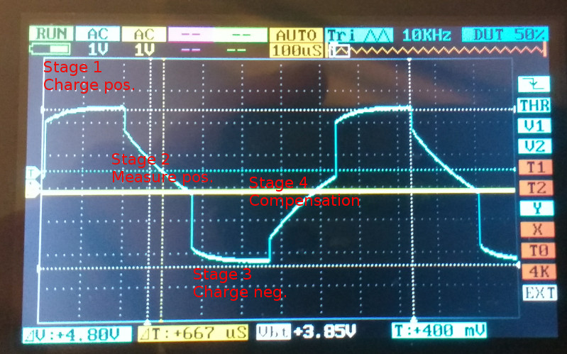
What I noticed as well is the sharp drop in voltage on CapPos the moment it's switched from OUTPUT to INPUT. The pin's voltage drops by over 2V in just over 0.1µs. As the processor runs at 8 MHz one tick is 125 ns, so that's apparently within a single clock tick. This is the start of the positive discharge cycle (the negative one looks identical but then with a jump in voltage), and it's related to CapPos pin switching from OUTPUT to INPUT. After that a very small drop in voltage until the interrupt is triggered.

I would expect that when the capacitor is charged, and the pin switches from OUTPUT to INPUT, that the voltage level at that pin remains the same, as there is no channel for electric charge to move to. Repeating the test with a 22 nF capacitor showed the same voltage drop upon switching the pins, so it's not a pin capacitance (or I should see a marked difference in voltage drops as I change the capacitor value).

Further testing shows that this voltage drop is closely related to the EC resistance. When placing a 330Ω resistor between CapPos and EC pin (R2 in the schematic), I get almost 2.5V drop. When I decrease that value to 165Ω (two 330Ω resistors in parallel) this is more, and I don't get the interrupt any more: the pin drops LOW before I can enable the interrupt (which is a few clock cycles later). Increasing this resistance to 2k2 gives me a voltage drop of barely 1V at the start of the discharge cycle. This image is the waveform measured with 2k2 for EC resistor.


This drop/jump in voltage I see ever time the CapPos and EC pin change between INPUT and OUTPUT. The exact same behaviour is observed for both NodeMCU and my Pro Mini (ATmega328), though those two processors it's apparently not as great a change so they still record the interrupt.

Also at the end of stage 2 and stage 4 I sometimes see artefacts in the scope signal: peaks flashing by to +5V or 0V. That's another thing to look into.

In the next few days I hope to get a working data cable, so at least I can get the waveforms as proper image.

Schematic:

Code used for these tests:

// ATtiny84a
//

#define CAPPOS PB0                            // digital pin for cap and EC probe - PB0.
#define INTERRUPT PCINT8                      // The pin change interrupt linked to PB0.
#define CAPNEG PB1                            // digital pin for cap and analog in for NTC probe.
#define ECPIN PB2                             // digital pin for EC probe.
#define CHARGEDELAY 200                       // Time in microseconds it takes for the cap to charge; at least 5x RC.
//                                            // 100 nF & 330R resistor RC = 33 us.
#define EC_TIMEOUT 2000                       // Timeout for the EC measurement in microseconds.

// Time scale to go from clock pulses to microseconds.
// 8 MHz clock: 8 = 2^3 pulses per microsecond, TIMESCALE 3.
#define TIMESCALE 3

volatile uint16_t dischargeCycles = 0;

void setup() {

  // Set up the timer
  TCCR1A = 0;
  TCCR1B = 0;
  TCCR1B |= (1 << CS10);                      //  Set to no prescaler

  GIMSK |= (1 << PCIE1);                      // Enable pin change interrupts on the PB pins.
  //  SREG |= (1 << 7);                           // Globally enable interrupts.

}

void loop() {
  uint32_t startTime = 0;
  for (uint8_t i = 0; i < 64; i++) {

    // Stage 1: charge the cap, positive cycle.
    DDRB |= (1 << CAPPOS);                        // CAPPOS output.
    DDRB |= (1 << CAPNEG);                        // CAPNEG output.
    DDRB &= ~(1 << ECPIN);                        // ECPIN input.
    PORTB |= (1 << CAPPOS);                       // CAPPOS HIGH: Charge the cap.
    PORTB &= ~(1 << CAPNEG);                      // CAPNEG LOW.
    PORTB &= ~(1 << ECPIN);                       // ECPIN pull up resistor off.
    TCNT1 = 0;
    while (TCNT1 < (CHARGEDELAY << TIMESCALE)) {}

    // Stage 2: measure positive discharge cycle by measuring the number of clock cycles it takes
    // for pin CAPPOS to change from HIGH to LOW.
    dischargeCycles = 0;
    TCNT1 = 0;                                    // Reset the timer.
    DDRB &= ~(1 << CAPPOS);                       // CAPPOS input.
    PORTB &= ~(1 << CAPPOS);                      // CAPPOS pull up resistor off.
    DDRB |= (1 << ECPIN);                         // ECPIN output.
    PCMSK1 |= (1 << INTERRUPT);                   // Set up the pin change interrupt on CAPPOS.

    while (TCNT1 < (EC_TIMEOUT << TIMESCALE)) {
      if (dischargeCycles) {
        break;
      }
    }
    PCMSK1 &= ~(1 << INTERRUPT);                  // Clear the pin change interrupt on CAPPOS.

    // Stage 3: charge the cap, negative cycle.
    DDRB &= ~(1 << ECPIN);                        // ECPIN input
    DDRB |= (1 << CAPPOS);                        // CAPPOS output
    PORTB &= ~(1 << CAPPOS);                      // CAPPOS LOW
    PORTB |= (1 << CAPNEG);                       // CAPNEG HIGH: Charge the cap
    TCNT1 = 0;
    while (TCNT1 < (CHARGEDELAY << TIMESCALE)) {}

    // Stage 4: discharge the cap, compenstation cycle.
    DDRB &= ~(1 << CAPPOS);                       // CAPPOS input
    DDRB |= (1 << ECPIN);                         // ECPIN output
    PORTB |= (1 << ECPIN);                        // ECPIN HIGH

    // delay based on dischargeCycles
    TCNT1 = 0;
    if (dischargeCycles) {
      while (TCNT1 < dischargeCycles) {}
    }
    else {
      while (TCNT1 < (CHARGEDELAY << TIMESCALE)) {}
    }
  }
}

ISR(PCINT1_vect) {
  dischargeCycles = TCNT1;
  PCMSK1 &= ~(1 << INTERRUPT);                      // Clear the pin change interrupt on CAPPOS.
}