Pin Change Interrrupt restarting attiny85

TLDR: PCINT0_vect is the interrupt vector for all pin change interrupts on the attiny85. I had originally used PCINT1_vect, which caused it to restart and run setup again.

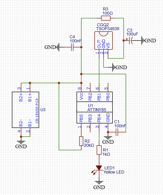
I'm working on an IR beam break trigger that I will eventually connect to a DSLR. One attiny85 pulses a 38kHz signal that is detected by a second attiny85 that gets a signal as a pin change interrupt from an IR receiver.

The basic logic is this:
timer1 counts up to 25ms
if it overflows, then it triggers an interrupt that starts the photo routine

The IR pulse comes in about every 21ms.
A pin change from the IR receiver resets the timer one counter so it doesn't reach 25ms.

That was behaving exactly like I wanted it to, so I started working on a way for the IR emitter end to tell the receiver end it was shutting down when the battery voltage got too low. I added an LCD to get some feedback on what was happening with variables.

When I added the LCD, though, the response time of the receiver end increased significantly and the LCD backlight would blink. After removing any attempts to enter sleep mode and making sure there were no commands to the LCD anywhere but in setup(), the behavior didn't change. I removed everything to do with the LCD and replaced the LCD initialization code with code that turns on the LED standing in for the camera for 5 seconds to see if the set up was running again.

Currently, the camera/LED signal turns on for 5 seconds every time that the IR receiver pin change interrupt gets triggered and will stay on if it continues to receive the IR pulses. It seems like the device is restarting. I made sure that the brown out detector and the watchdog timer were disabled and I added a pullup resistor to the reset pin. I think that narrows it down to a power on reset or a crash that restarts everything.

I've been trying to figure out what I did to break things, but I'm starting to wonder if it's been doing this the whole time and the setup code just didn't take a noticeable amount of time. Either way I'm not sure what's going on at this point. Schematic and code below.

Using Arduino uno as ISP and the ATTiny Core from Konde. Speed is at 1MHz.

#include <avr/io.h>
#include <avr/interrupt.h>

const int shutter = 4;
int num_photo = 4; //will later take input to set during setup
int photo_deltaT = 1000; //will later take input to set during setup
volatile int tripwire = 0;

void setup() {
  
  //Interrupts setup
  cli();

  //Timer 1 40Hz (T=25ms) setup
  TCCR1 = 0; // Stop Timer1
  TCNT1 = 0; // Reset Timer1 count
  GTCCR |= (1<<PSR1); // Reset prescaler for Timer1
 
  //Turn on fast PWM mode and set prescaler to 128. See register description in section 12.3 of ATTiny85 datasheet
  TCCR1 |= (1<<PWM1A)|(1<<CS13); 

  //Set TOP value of counter to 194 to get a 40Hz signal. Follow formula on p.87 of datasheet.
  OCR1A = 194;  

  TIMSK |= (1<<OCIE1A); // Enable OCRA interrup on Timer 1

  //Pin change interrupt setup
  GIMSK |= (1<<PCIE); //Enable pin change interrupts
  PCMSK |= (1<<PCINT1); //Enable pin change interrupt on PB1
  
  WDTCR &= ~(1<<WDE) & ~(1<<WDIE); //disable watchdog timer
  MCUCR |= (1<<BODS) | (1<<BODSE); //disable  brownout detector

  sei();

  pinMode(shutter,OUTPUT);
  
  //test signal to see if setup runs again
  digitalWrite(shutter,HIGH); //sends a signal to the shutter release to take a picture
  delay(5000); //wait 5s
  digitalWrite(shutter,LOW); //turns off signal to shutter release
}

void loop() {
  // put your main code here, to run repeatedly:
  if (tripwire == 1){
    photo();
    tripwire = 0;
  }
}

ISR(TIMER1_COMPA_vect){
  tripwire = 1;
}
ISR(PCINT1_vect){
  TCNT1 = 0;
}

void photo(){
  GIMSK &= ~(_BV(PCIE));
  
  for (int i = 0; i < num_photo; i++){ //sets a loop to repeat the number of photos taken per trigger
    digitalWrite(shutter,HIGH); //sends a signal to the shutter release to take a picture
    delay(50); //wait 50ms
    digitalWrite(shutter,LOW); //turns off signal to shutter release
    delay(photo_deltaT - 50); //sets the delay time between pictures
  }
  TCNT1 = 0;
  GIMSK |= (1<<PCIE);
  
}

Where is power introduce?

It looks like once power is introduced, you are using the ATtiny85 microcontroller as a power supply.

You're talking about for the LED, right? Currently it is hooked up as shown, but that was a simplification made for uploading the schematic here. It behaves the same as before, though. In the circuit that originally displayed the behavior, PB4 sends a signal through an optocoupler and resistor to ground, and the other side of the optocoupler had voltage input from the batteries, the LED, and the resistor.

I see no power supply in your drawing.

Ah, sorry. U3 on the left there has 2 18650 batteries in parallel. They're doing around 4V at their current state of charge.

Ah. I missed that. So obvious now.

You should make the ISR only set a flag to indicate photo() needs to happen. Variables that change (the flag) in an ISR should be global type volatile, and when entering the ISR, cli(), then before exiting the ISR sei()... and never have delay() in an ISR.

That detector, the TSOP34838, reacts badly to a continuous 38kHz signal (if that is what you are sending). This is because it attempts to filter out interference say from fluorescent lights etc. and a continuous signal confuses it.
The data sheet https://www.vishay.com/docs/82489/tsop322.pdf will tell you what it can tolerate. The solution is to send say 20 pulses at 38kHz then pause for a few ms then resume in a continuous cycle. Alternatively, look for a beam break sensor such as TSSP58038 which does not have interference suppression.

EDIT

I'd probably have done the receiver more simply using millis() instead of using a hardware timer. Just read the IR receiver pin in the loop. On every loop iteration if the pin is LOW, you (re)set the timer, something like myTimer = millis() where myTimer is a static or global uint32_t. This means that myTimer always contains the time of the last successful transmisison. You then test the timer regularly to see if has expired if (millis() - myTimer > X) . . . (indicating no transmission received / beam break for Xms). If so, activate the trigger. If you want to suppress further actions for a specific interval, set another timer.
Having said that, it is also interesting to go deeper into the ATtiny85, manipulating timer registers etc. without using libraries.

Thanks for the suggestions.

That's pretty much what I'm doing. In the code I posted, the only thing in the pin change ISR is resetting the timer 1 counter. The timer 1 ISR just sets a value called tripwire, which the loop code checks for.

Sorry, my original post wasn't clear about that. The other attiny85 turns on the signal for 500 microseconds and goes to sleep for 20 milliseconds before waking up to do it again. That gives a sufficient response time that I don't think I need to change sensors to one that can handle a constant signal.

I've been through a couple iterations, and I think I tried something like this initially, but I can't remember what wasn't working about it. At the same time, I was already figuring out the timers for making the 38kHz signal, so that seemed like a good solution that would have a snappy response time.

I just tested it again, but moved the input over to the INT0 pin and reconfigured the interrupt to a LOW external interrupt. All I changed in the code was this:

/*
  //Pin change interrupt setup
  GIMSK |= (1<<PCIE); //Enable pin change interrupts
  PCMSK |= (1<<PCINT1); //Enable pin change interrupt on PB1
*/
  //Set up External interrupt for LOW signal on INT0/pin 2
  MCUCR &= ~(_BV(ISC00)); //LOW mode
  MCUCR &= ~(_BV(ISC01)); //LOW mode
  GIMSK |= (1<<INT0); //Enable external interrupt on INT0
/*
ISR(PCINT1_vect){
  TCNT1 = 0;
}
*/
ISR(INT0_vect){
  TCNT1 = 0;
}

If I do that, everything works great. No repeated 5s signal on the LED indicating that it restarted. It's tempting to call it there, but I would like to be able to use an LCD and some buttons to set the number of pictures taken and the time between them on startup. The INT0 and the SCL are on the same pin, though, so I'm hoping I can get the pin change interrupt to work.

Is having two pin changes 500 microseconds apart too close? I don't see why it would be as the datasheet seems to say that the timing for a PCINT is about 3 clock cycles (if I'm reading this right). With a clock source of 1MHz, there should be 500 clock cycles in 500 microseconds.

The timer one counter would only make it to 3 or 4 before getting reset again when the sensor goes high in the absence of an IR pulse, but I tried reading the pin in the interrupt to see if it was LOW and only resetting the timer then, but that didn't help anything.

Any ideas as to what is breaking when I change from an external interrupt to a pin change interrupt?

Maybe it is the behaviour of the interrupt. This is how I understand the AVR:

A pin change interrupt triggers once on a transition LOW->HIGH or HIGH->LOW.
An edge triggered interrupt (rising or falling) triggers once during the edge.
A LOW external interrupt triggers continuously while the pin is LOW.

If that does not explain it, I'll look more closely at your code.

Well, that's not entirely it, it seems. I changed the external interrupt to toggle mode, and it is still doing what it is supposed to be doing and not restarting every time the interrupt triggers. Something specific to the pin change interrupt (or my implementation of it). I changed

  //Set up External interrupt for LOW signal on INT0/pin 2
  MCUCR &= ~(_BV(ISC00)); //LOW mode
  MCUCR &= ~(_BV(ISC01)); //LOW mode
  GIMSK |= (1<<INT0); //Enable external interrupt on INT0

to

  //Set up External interrupt for TOGGLE signal on INT0/pin 2
  MCUCR |= (_BV(ISC00)); //TOGGLE mode
  MCUCR &= ~(_BV(ISC01)); //TOGGLE mode
  GIMSK |= (1<<INT0); //Enable external interrupt on INT0

I can't see how you have masked the pin change interrupt so it responds only to the pin(s) you want to respond to.
Can you state which pins (you've only got 5 to play with) that you want to use for your application, including the screen and the IR sensor.
Show also your latest code.

Referring to your following diagram (Fig-1). I woold like to ask you few things as I have not understood your exact problem.


Figur-1:

1. CGQ2 is the IR Receiver -- correct?

2. The IR Receiver receives a band 38 kHz IR Signal from a remote IR Transmitter -- Correct?

3. What is the duration of the 38 kHZ IR signal band of Step-2?

4. After how long delay, the IT Transmitter sends the next band?

5. After the signal being decoded by the IR Receiver, the recoded signal interrupts the ATtiny85 over PB1-pin --- is this Correct?

6. The MCU should be interrupted and shoud go to ISR() routine and shoud do someting -- do all these happen?

Please, let me where are you failing in context of all the above steps.

Thanks for co-operation.

I do have the mask declared in the original code, setting PCINT1 to 1. I did not declare the others to be 0, but I just tried that and still have the same problem.

All 5 pins will be in use if I am able to get this working how I want.

PB0 = SDA -> LCD
PB1 = PCINT1 <- IR Sensor
PB2 = SCL -> LCD
PB3 <- Button input
PB4 -> Shutter release to camera

Here is the code, both the working code with a toggle external interrupt and the code with the pin change interrupt where I'm having problems.

Pin change code

#include <avr/io.h>
#include <avr/interrupt.h>

const int shutter = 4;
int num_photo = 4; //will later take input to set during setup
int photo_deltaT = 1000; //will later take input to set during setup
volatile int tripwire = 0;
volatile byte x = 0;


void setup() {
  
  //Interrupts setup
  cli();

  //Timer 1 40Hz (T=25ms) setup
  TCCR1 = 0; // Stop Timer1
  TCNT1 = 0; // Reset Timer1 count
  GTCCR |= (1<<PSR1); // Reset prescaler for Timer1
 
  //Turn on fast PWM mode and set prescaler to 128. See register description in section 12.3 of ATTiny85 datasheet
  TCCR1 |= (1<<PWM1A)|(1<<CS13); 

  //Set TOP value of counter to 194 to get a 40Hz signal. Follow formula on p.87 of datasheet.
  OCR1A = 194;  

  TIMSK |= (1<<OCIE1A); // Enable OCRA interrup on Timer 1

  //Pin change interrupt setup
  PCMSK = 0;  //Clear PCMSK, disable all pin change interrupts 
  PCMSK |= (1<<PCINT1); //Enable pin change interrupt on PB1
  GIMSK |= (1<<PCIE); //Enable pin change interrupts

  WDTCR &= ~(1<<WDE) & ~(1<<WDIE); //disable watchdog timer
  MCUCR |= (1<<BODS) | (1<<BODSE); //disable  brownout detector

  sei();

  pinMode(shutter,OUTPUT);
  
  //test signal to see if setup runs again
  digitalWrite(shutter,HIGH); //sends a signal to the shutter release to take a picture
  delay(5000); //wait 5s
  digitalWrite(shutter,LOW); //turns off signal to shutter release
}

void loop() {
  // put your main code here, to run repeatedly:
  if (tripwire == 1){
    photo();
    tripwire = 0;
  }
}

ISR(TIMER1_COMPA_vect){
  tripwire = 1;
}

ISR(PCINT1_vect){
   TCNT1 = 0;
}

void photo() {
  GIMSK &= ~(1<<PCIE);
  
  for (int i = 0; i < num_photo; i++){ //sets a loop to repeat the number of photos taken per trigger
    digitalWrite(shutter,HIGH); //sends a signal to the shutter release to take a picture
    delay(50); //wait 50ms
    digitalWrite(shutter,LOW); //turns off signal to shutter release
    delay(photo_deltaT - 50); //sets the delay time between pictures
  }
  TCNT1 = 0;
  GIMSK |= (1<<PCIE);
  
}

External interrupt code

#include <avr/io.h>
#include <avr/interrupt.h>

const int shutter = 4;
int num_photo = 4; //will later take input to set during setup
int photo_deltaT = 1000; //will later take input to set during setup
volatile int tripwire = 0;
volatile byte x = 0;


void setup() {
  
  //Interrupts setup
  cli();

  //Timer 1 40Hz (T=25ms) setup
  TCCR1 = 0; // Stop Timer1
  TCNT1 = 0; // Reset Timer1 count
  GTCCR |= (1<<PSR1); // Reset prescaler for Timer1
 
  //Turn on fast PWM mode and set prescaler to 128. See register description in section 12.3 of ATTiny85 datasheet
  TCCR1 |= (1<<PWM1A)|(1<<CS13); 

  //Set TOP value of counter to 194 to get a 40Hz signal. Follow formula on p.87 of datasheet.
  OCR1A = 194;  

  TIMSK |= (1<<OCIE1A); // Enable OCRA interrup on Timer 1

  //Set up External interrupt for TOGGLE signal on INT0/pin 2
  MCUCR |= (1<<(ISC00)); //TOGGLE mode
  MCUCR &= ~(1<<(ISC01)); //TOGGLE mode
  GIMSK |= (1<<INT0); //Enable external interrupt on INT0

  WDTCR &= ~(1<<WDE) & ~(1<<WDIE); //disable watchdog timer
  MCUCR |= (1<<BODS) | (1<<BODSE); //disable  brownout detector

  sei();

  pinMode(shutter,OUTPUT);
  
  //test signal to see if setup runs again
  digitalWrite(shutter,HIGH); //sends a signal to the shutter release to take a picture
  delay(5000); //wait 5s
  digitalWrite(shutter,LOW); //turns off signal to shutter release
}

void loop() {
  // put your main code here, to run repeatedly:
  if (tripwire == 1){
    photo();
    tripwire = 0;
  }
}

ISR(TIMER1_COMPA_vect){
  tripwire = 1;
}

ISR(INT0_vect){
  TCNT1 = 0;
}

void photo() {
  GIMSK &= ~(1<<INT0);
  
  for (int i = 0; i < num_photo; i++){ //sets a loop to repeat the number of photos taken per trigger
    digitalWrite(shutter,HIGH); //sends a signal to the shutter release to take a picture
    delay(50); //wait 50ms
    digitalWrite(shutter,LOW); //turns off signal to shutter release
    delay(photo_deltaT - 50); //sets the delay time between pictures
  }
  TCNT1 = 0;
  GIMSK |= (1<<INT0);
  
}

The pin change interrupt mask will look something like this example: PCMSK = 0b00001000; // PB3

Yes, that is the IR receiver.

Correct. Technically it is 38.4kHz, but it is well within the frequency seen by the sensor.

The signal is on for 500 microseconds and is sent again after 20 milliseconds

Yes, that is the goal. It works as an external interrupt on PB2, but I want to use PB2 for an LCD screen, so I am trying to make this work with a pin change interrupt on PB1.

This is where there is a problem. There is definitely an interrupt, but instead of the expected behavior of calling the ISR() which resets the timer1 counter, the whole program restarts. I've confirmed this by adding a 5 second signal to an LED during void setup().

What should happen is that while the IR signal is being received approximately every 21 milliseconds, the LED will stay off because the timer never reaches the TOP value of 194. Once the signal stops, the timer will overflow 25 milliseconds later and trigger the photo() routine.

What happens with the pin change interrupt configuration is that while the IR signal is being received, the LED never visibly goes off. Here is what I believe it is doing:
-starts the program
-enables the interrupts
-turns on LED for 5 seconds in setup()
-is interrupted within 21 milliseconds
-the program restarts
-enables the interrupts
-turns on LED for 5 seconds in setup()...

If the signal is turned off,
-the 5 second delay finishes
-timer1 overflows
-photo() routine starts

The timer will keep overflowing and the photo routine will keep running until I turn the signal back on. Then
-photo() routine finishes
-PC interrupts are re-enabled
-is interrupted within 21 milliseconds
-the program restarts
-enables the interrupts
-turns on LED for 5 seconds in setup()...

I can try setting it in binary, but it should be equivalent to what I have

  PCMSK = 0;  //Clear PCMSK, disable all pin change interrupts 
  PCMSK |= (1<<PCINT1); //Enable pin change interrupt on PB1

I tried the binary assignment, no change. I also moved the sei() to the very end of setup(). The behavior changed slightly.

Now if I turn the signal off, the 5 second delay no longer has to finish before it moves into the photo() routine, though there is still a noticeable delay. The light stays on as long as the IR signal is turned on, though.

1. Let us first practice the operation of PCINT1 (Pin Change Interrupt for PPin-6) of ATtiny85.

(1) It is good if you have a Digispark ATtiny85 Dev Board (Fig-1 or Fig-2).
DigisparkAttiny85Board
Figure-1:

Attiny85DevBoard
Figure-2:

(2) Connect a Button at PB1-pin using an external pull-down register (Fig-3). Also comnect an I2CLCD.


Figure-3:
(3) Upload the following sketch.

#include<LiquidCrystal_I2C.h>
LiquidCrystal_I2C lcd(0x27, 16, 2);

#define PCINT1 1  //PB1
volatile bool flag = false;

void setup()
{
  lcd.begin();
  lcd.backlight();
  lcd.setCursor(0, 0); //DP0, TopLine
  lcd.print("System is Ready.");
  pinMode(PCINT1, INPUT);  //external pull-down
  bitSet(GIMSK, PCIE);  //Pin Chage interrupt logic is enabled
  bitSet(PCMSK, PCINT1);  //Pin Chnage Interrupt logic for PPin-1 is enabled
  interrupts();  //Global interrupt logic is enabled
}

void loop()
{
  if (flag == true)
  {
    int y = digitalRead(PCINT1);
    if (y == HIGH)
    {
      lcd.setCursor(0, 1);
      lcd.print("Yes! PCINT1 Int.");
      delay(5000);
      lcd.clear();
      lcd.setCursor(0, 0); //DP0, TopLine
      lcd.print("System is Ready.");
      flag = false;
    }
  }
}

ISR(PCINT0_vect)
{
  flag = true;
}

(4) Check that "System is Ready." message appeared on Top Line of LCD.

(5) Gently, press and release the Button (the Interrupting Device).

(6) Check that the message ("Yes! PCINT1 Int." has appeared on Bottom Line of LCD.

If you don;t have Digispark Dev Board, you can use your naked ATtiny85 and AVR Programmer to exercise the above Tutorial.

Good Luck!

I don't think that that is sufficient to disable the watchdog. (But you said the WDT isn't enabled at the fuse level, anyway, right?)

From the datasheet:

To disable an enabled Watchdog Timer, the following procedure must be followed:

  1. In the same operation, write a logic one to WDCE and WDE. A logic one must be writ- ten to WDE regardless of the previous value of the WDE bit.
  2. Within the next four clock cycles, in the same operation, write the WDE and WDP bits as desired, but with the WDCE bit cleared.

In photo(), you disable the pin change interrupt via GIMSK, but the HW logic continues to operate and probably sets INTF0 in GIFR while you're in delay(), so that a new interrupt will occur immediately after you re-enable the interrupt. I don't see any reason that that should be fatal with the current code, but you probably want to want to clear the bit in INTF0 just before you set GIMSK.

Your PC interrupt demo sketch works fine. I changed it slightly to have a pull up resistor and be triggered when it goes LOW, since that is more similar to the sensor.