I moved a working project from attiny85 to the attiny84 as I needed more pins
I downloaded the latest version of the Arduino Tiny from github
For some reason the pin mapping seems to be wrong. (for me)
E.g Using the following code I would expect PA4 to blink but PA6 does instead.
Is there a logical answer?
I have the correct board selected etc and have burnt the boot loader.
Sorry if this is a stupid question.
Rob
/*
  Blink
  Turns on an LED on for one second, then off for one second, repeatedly.

  This example code is in the public domain.
 */


int led = PA4;

// the setup routine runs once when you press reset:
void setup() {
  // initialize the digital pin as an output.
  pinMode(led, OUTPUT);
}

// the loop routine runs over and over again forever:
void loop() {
  digitalWrite(led, HIGH);   // turn the LED on (HIGH is the voltage level)
  delay(1000);               // wait for a second
  digitalWrite(led, LOW);    // turn the LED off by making the voltage LOW
  delay(1000);               // wait for a second
}
Moderator edit: </mark> <mark>[code]</mark> <mark>
If you look at an Uno for example, digital pin 12, what does that correspond to?
There is a mapping going on in the core (both Arduino and Tiny) which convert from a 'digital pin number' to an 'avr register name and bit'
Somewhere in the core you will find a file which describes the 'digital pin' numbers and how they map to the real pin numbers.
Now if you want to know what PA4 means, then try this:
const byte led = PA4;

// the setup routine runs once when you press reset:
void setup() {
  // initialize the digital pin as an output.
  pinMode(led, OUTPUT);
}

// the loop routine runs over and over again forever:
void loop() {
  PORTA |= _BV(led);   // turn the LED on (HIGH is the voltage level)
  delay(1000);               // wait for a second
  PORTA &= ~_BV(led)    // turn the LED off by making the voltage LOW
  delay(1000);               // wait for a second
}
Digital pin 4 would make sense if I saw D4 in any of the references I'm using.
I thought Arduino did all the clever stuff and I could just reference the pic without having to resort to reading and learning
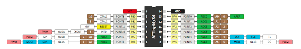
I was using the following attached files as my reference.
My problems started when I could address PA0 to PA5 but not PA6 & PA7
To test the PCB I had made I used the blink sketch to test each port, (Relay, Piezo, LEDs) I could address PA0 to 5 but not 6 & 7 (6&7 go to a Bipolar LED).
Having just come back to Arduino after a year break I am rusty and tried every variaition to talk to the pins.
In hind sight I think I have made a bad choice of what pins I use.
I thought Arduino did all the clever stuff and I could just reference the pic without having to resort to reading and learning
It does. You just have to have the right pic.
I was using the following attached files as my reference.
I assume that latter image is the pin mapping for the core I referenced in Reply #3 but I honestly don't know.
My problems started when I could address PA0 to PA5 but not PA6 & PA7
They should be digital pins 10 through 5 and digital pins 4 and 3.
To test the PCB I had made I used the blink sketch to test each port, (Relay, Piezo, LEDs) I could address PA0 to 5 but not 6 & 7 (6&7 go to a Bipolar LED).
PA6 is digital pin 4. PA7 is digital pin 3.
The digital pins form a U starting with the upper-left physical pin and ending with the upper-right; just like the ATmega328 pin mapping.
The analog numbering matches the PA-number; just like the ATmega328 (port C). PA0 is analog input 0, PA1 is analog input 1, etcetera.
I have now looked at the link you sent and tested and as always you are correct.
I admit I don't fully understand how addressing the pins D0 to D10 is derived but I assume it's somewhere within the Tiny code.
Where would i find this information in future for other ATTinys?
Lastly I'm using serial for debugging which by default comes out on D0, I have tried various things to move this but again I can't figure this out.
Is this possible?
I thought Arduino did all the clever stuff and I could just reference the pic without having to resort to reading and learning
It does. You just have to have the right pic.
I am too confused with pin numbering to be used in Arduino IDE. Is there a place where one can find all those PAx and PBx pins neatly mapped against pin numbers to be used in Arduino IDE ? I think the beauty of Arduino and its family chips is that one can start using them without deep knowledge of electronics. But failure to find clear pin mappings is a big disadvantage, I believe.
Hi,
I am not sure I know what core means. I am looking for pinout for Attiny84 to be programmed on Arduino IDE 1.0.5. I believe I found the description I was looking for on this site: