[Solved] Switched from "attiny" to "ATTinyCore" package, can't blink an LED now

Solution: The primary issue was choosing the wrong setting for "pin orientation" with respect to the values I used in my code. There are lots of good details for beginners in the responses below regarding pins, bits, and naming...

I've been working with the ATTiny85 then ATTiny84 and next I want to try the ATTiny841.

I just realized that the "attiny" package I was using in the Arduino 1.6.12 development environment doesn't support the 841 chip. So after a little searching, I found the "ATTinyCore" package. However, I'm having trouble getting it to work at all with programs (sketches?) that I know are valid.

I'm using a simple blink program with the ATTiny84 as a test.
Here is the (datasheet). Here is my code:

int blinkPin = PA6;

void setup()
{
  pinMode(blinkPin, OUTPUT);
}

void loop()
{
  digitalWrite(blinkPin, HIGH);
  delay(250);
  digitalWrite(blinkPin, LOW);
  delay(250);
}

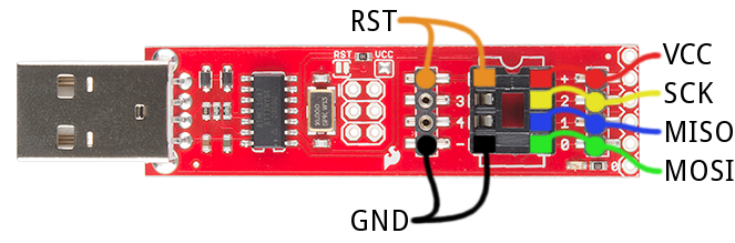
I'm using a SparkFun TinyAVR Programmer since I originally thought I'd be using ATTiny85 chips. I didn't want to buy another programmer so I've run wires from the pins as shown here to a breadboard with my ATTiny84 chip using these pins.

I switched from Arduino 1.6.12 to Arduino 1.6.9 as recommended on the ATTinyCore github page.

These are my settings that work with the "attiny" package:

These are my settings that are not working with "ATTinyCore":

I've also observed the following

If I burn the bootloader and upload the code with the "attiny" package, the light blinks.
If I do the same with the "ATTinyCore", the light does nothing / always off.
If I burn the bootloader from ATTinyCore and upload with attiny, the light also blinks.
If I burn the bootloader from attiny and upload with ATTinyCore, the light stays off.

Finally, with both packages I observe the little LED on my programmer blinking as the program uploads to the chip. So everything appears normal up to that point and I can tell things are happening. The difference is when the upload is finished, it immediately starts running and I see my programmer's LED start blinking when things work and the LED just stays off when things do not work.

If anyone has suggestions, I would appreciate it!

Thanks,
Bill

The problem is this:

bill85pi:

int blinkPin = PA6;

In the file iotnx4.h is the line:

#define PA6 6

This is the bit of PA6.

The attinycore happens to assign Arduino pin 6 to PA6, however if you had tried this with any of the PORTB pins you would also have found it didn't work with the attinycore. Arduino functions use Arduino pin numbers. To find the correct Arduino pin number to use there is a handy diagram in the ATTinyCore readme(GitHub - SpenceKonde/ATTinyCore: Arduino core for ATtiny 1634, 828, x313, x4, x41, x5, x61, x7 and x8):


So as you can see there are two different Pin Mappings available in ATTinyCore. This can be set in the Tools > Pin Mapping menu. The default one is called Counterclockwise(like ATTinyCore). That's the one you have selected currently. It's the numbers in the diagram marked as "Alternative pinout". That pinout assigns Arduino pin number 4 to PA6. The other option is "Clockwise (like damellis core)". This has the same pinout as the attinycore, which assigns Arduino pin number 6 to PA6, so changing to that selection will make your sketch work but as I said, using PA6 is not right so you need to change to using Arduino pin numbers.

Thanks for the reply and the tip regarding bit position vs. pin number.

Indeed, this works for the counter-clockwise configuration:

int blinkPin = 4;

and this works for the clockwise configuration:

int blinkPin = 6;

I revisited the readme file and the spec sheet. I'm still having trouble grasping a couple of things.

The readme explains

Note that analog pin numbers (ex A0 ) cannot be used with digitalWrite()/digitalRead()/analogWrite() - all pins have a digital pin number. Analog pin number should only be used for analogRead().

However, I'm not clear on what the digital pin numbers are. Would that be the ones marked as "Arduino Pin" numbers? If so, the diagram defines the Arduino Pin number for port pin PA6 as:

"4/A6" for Alternate Pinout (which I now know is counter-clockwise, like ATTinyCore, and the default)
"6/A6" for standard(?) Pinout (which would be clockwise, like damellis)

Does this mean I can use either 4 or A6 for counter-clockwise orientation? I tried 4 and it works. I tried A6 and it did not work. Or, does this mean something different (like 4 for pin numbers and A6 for bit numbers, or 4 is digital and A6 is analog, ... ?). Any help here would be great so I can use the proper notation in my programs.

Additionally, I'm still a little confused about the clockwise vs counter-clockwise capability. Since I was using the ATTinyCore "package" in Arduino, and the ATTinyCore option was selected by default, I thought this was the correct thing to use.

This question is probably too basic for me to search it properly, but under what circumstance would I want to use the alternate pin mappings? Since the are default, I'm guessing they are maybe the 'recommended' setting for using the ATTinyCore. However, it is a little confusing that they don't align with the ATTiny84 spec sheet. So I'm assuming there is a good reason to deviate but I'm having trouble understanding what it is. I saw a blurb somewhere that it was related to ADC, but it hasn't clicked for me yet.

Thanks again!
Bill

bill85pi:
However, I'm not clear on what the digital pin numbers are. Would that be the ones marked as "Arduino Pin" numbers?

Correct, they are the ones in the blue ovals.

bill85pi:
Does this mean I can use either 4 or A6 for counter-clockwise orientation?

Use 4 for digitalWrite(), digitalRead(), analogWrite(), or any other usage of the pin that doesn't involve analog input. Use A6 for analogRead() or any other analog usage of the pin. It seems wrong to use the digital pin number for analogWrite() but that function name is not really correct. analogWrite() actually is PWM output on the pin, not analog, thus digital pin number is correct.

bill85pi:
Additionally, I'm still a little confused about the clockwise vs counter-clockwise capability. Since I was using the ATTinyCore "package" in Arduino, and the ATTinyCore option was selected by default, I thought this was the correct thing to use.

You can use either one, it's just a matter of preference unless you have a board with the pin numbers on the silkscreen or something like that. Arduino pins numbers are just arbitrary numbers assigned to the IO pins of the microcontroller because the concept of identifying the pins by port and bit is more complicated for beginners. The counterclockwise pin mapping used to be the only one that ATTinyCore had but a lot of people use the attiny core so the author added that option.

bill85pi:
it is a little confusing that they don't align with the ATTiny84 spec sheet.

The ATtiny84 spec sheet doesn't say anything about it. As I said, IO pin numbers are just an abstraction used by the Arduino core API. Atmel's way of identifying pins is by port and bit, for example PA6 is bit 6 of PORTA. There are physical pin numbers but those are not limited to IO pins and they will be different depending on the chip package so it makes no sense to base Arduino pin numbers on those. If you don't want to use Arduino pin numbers you don't have to but then you need to do direct port manipulation, you need to use Arduino pin numbers for digitalWrite(), etc.

Thanks for the very helpful explanations! I'm starting to get the hang of this now.

Now that I understand the port pins (PA3, PB2) shouldn't be used as arguments for Arduino functions, things make a lot more sense. Since they work in many cases for certain configurations, I can see why I got that mixed up in my head early on.

I appreciate all the feedback!
Bill