Attiny85 Direct Port Toggling Problem (Tone multiplexing)

I have successfully programmed an Attiny85 to produce multiple channels of audio (Horray!).

Although it's only 2, and I need help with the third. For some reason PB2 is not toggled, and PB3 & PB4 just over-lap on PB1 & PB0 and create an awful sound.

I don't know if it has something to do with the code "PORTB ^= PBx", I'm not sure if this is the correct way to toggle pins. Since PB0 & PB1 are the only ones working properly, maybe I'm switching between pins 0 & 1, instead of toggling them?

#include "Tone.h"

unsigned int counter[5];

unsigned int togglespeed[5];

void setup()
{
	togglespeed[0] = 32768 / NOTE_F5;
	togglespeed[1] = 32768 / NOTE_C5;
	togglespeed[2] = 32768 / NOTE_E4;
	togglespeed[3] = 32768 / NOTE_C4;
	togglespeed[4] = 32768 / NOTE_E3;
	
	// Set timer1 to CTC mode, the max prescaler speed, and clear the OC1A pin.
	TCCR1 = 1 << CTC1 | 2 << COM1A1 | 1;

	// Set the timer overflow interrupts on timer1
	TIMSK = TIMSK | 1 << TOIE1;
	TIFR = TIFR | 1 << TOV1;

	pinMode(0,	 	OUTPUT);
	pinMode(1,	 	OUTPUT);
	pinMode(2,	 	OUTPUT);
	pinMode(3,	 	OUTPUT);
	pinMode(4,	 	OUTPUT);

}

ISR(TIMER1_OVF_vect)
{

	counter[0]++;
	counter[1]++;
	counter[2]++;
	counter[3]++;
	counter[4]++;
	
	if(counter[0] >= togglespeed[0])
	{
		PORTB ^= PB0;
		counter[0] = 0;
	}
	if(counter[1] >= togglespeed[1])
	{
		PORTB ^= PB1;
		counter[1] = 0;
	}
	if(counter[2] >= togglespeed[2])
	{
		PORTB ^= PB2;
		counter[2] = 0;

	}
}

void loop()
{


}

Note: this "Tone.h" file only contains the pitch definitions.

Thanks.

I think this should be

PORTB ^= (1<<PB0);

because PB0 is the bit number of the pin in the port. In order to manipulate PORTB, you need first to turn the pin number into a pin "mask" (a byte where the bit corresponding to the pin number is set to 1).

By the way, I believe there is a slightly more efficient way to do this:

PINB = (1<<PB0);

If you want some help with using arrays properly, just ask. Right now, you are using arrays but not getting any advantage from it.

I figured it out myself - but the solution is the same.

#include "Tone.h"
volatile byte *Port;
unsigned int counter[16];
unsigned int togglespeed[16];

void setup()
{
	togglespeed[0] = 32768 / NOTE_G5;
	togglespeed[1] = 32768 / NOTE_E5;
	togglespeed[2] = 32768 / NOTE_C5;
	togglespeed[3] = 32768 / NOTE_A4;
	togglespeed[4] = 32768 / NOTE_F4;

	// Set timer1 to CTC mode, the max prescaler speed, and clear the OC1A pin.
	TCCR1 = 1 << CTC1 | 2 << COM1A1 | 1;

	// Set the timer overflow interrupts on timer1
	TIMSK = TIMSK | 1 << TOIE1;
	TIFR = TIFR | 1 << TOV1;

	Port = portOutputRegister(digitalPinToPort(0));

	pinMode(0,	 	OUTPUT);
	pinMode(1,	 	OUTPUT);
	pinMode(2,	 	OUTPUT);
	pinMode(3,	 	OUTPUT);
	pinMode(4,	 	OUTPUT);


}

ISR(TIMER1_OVF_vect)
{

	counter[0]++;
	counter[1]++;
	counter[2]++;
	counter[3]++;
	counter[4]++;

	if(counter[0] >= togglespeed[0])
	{
		*Port = ((*Port) ^= (1UL << (PB0)));
		counter[0] = 0;
	}
	if(counter[1] >= togglespeed[1])
	{
		*Port = ((*Port) ^= (1UL << (PB1)));
		counter[1] = 0;
	}
	if(counter[2] >= togglespeed[2])
	{
		*Port = ((*Port) ^= (1UL << (PB2)));
		counter[2] = 0;
	}
	if(counter[3] >= togglespeed[3])
	{
		*Port = ((*Port) ^= (1UL << (PB3)));
		counter[3] = 0;
	}
	if(counter[4] >= togglespeed[4])
	{
		*Port = ((*Port) ^= (1UL << (PB4)));
		counter[4] = 0;

	}
}

void loop()
{


}

This code produces a nice F major 9th chord!

Thanks, but what did you mean about the arrays exactly?

Thanks, Paul.

Congrats for getting it working. But you made it so much more complex and inefficient, for no benefit. Always try to keep everything as simple as possible. That's the secret to working, reliable code.

You seem to have increased the array sizes to 16. I don't think attiny85 has that many pins, does it? :wink:

Just what I said. You are using arrays, but you might as well be using lots of individual variables. Your code never takes any advantage of the fact that they are arrays. As a result, the code is just as long as if you used individual variables. Every time you use the arrays, their indexes are hard-coded constants.

1 Like

Thanks Paul! I removed those silly arrays, they were for if I ever used a microcontroller with more pins.

#include "Tone.h"
unsigned int counter0,  counter1, counter2, counter3, counter4;
unsigned long togglespeed0, togglespeed1, togglespeed2, togglespeed3, togglespeed4;
long Factor = 32768;
void setup()
{
	// Set timer1 to CTC mode, the max prescaler speed, and clear the OC1A pin.
	TCCR1 = 1 << CTC1 | 2 << COM1A1 | 1;

	// Set the timer overflow interrupts on timer1
	//TIMSK = TIMSK | 1 << TOIE1;
	TIMSK |= (1 << TOIE1);
	TIFR = TIFR | 1 << TOV1;


	pinMode(0,	 	OUTPUT);
	pinMode(1,	 	OUTPUT);
	pinMode(2,	 	OUTPUT);
	pinMode(3,	 	OUTPUT);
	pinMode(4,	 	OUTPUT);


}

ISR(TIMER1_OVF_vect)
{

	counter0++;
	counter1++;
	counter2++;
	counter3++;
	counter4++;

	if(counter0 >= togglespeed0)
	{
		PINB = (1 << PB0);
		counter0 = 0;
	}
	if(counter1 >= togglespeed1)
	{
		PINB = (1 << PB1);
		counter1 = 0;
	}
	if(counter2 >= togglespeed2)
	{
		PINB = (1 << PB2);
		counter2 = 0;
	}
	if(counter3 >= togglespeed3)
	{
		PINB = (1 << PB3);
		counter3 = 0;
	}
	if(counter4 >= togglespeed4)
	{
		PINB = (1 << PB4);
		counter4 = 0;
	}
}
void loop()
{
	togglespeed0 = Factor / NOTE_FS5;
	togglespeed1 = Factor / NOTE_D5;
	togglespeed2 = Factor / NOTE_B4;
	togglespeed3 = Factor / NOTE_G4;
	togglespeed4 = Factor / NOTE_G3;
	delay(2000);
	togglespeed0 = Factor / NOTE_FS5;
	togglespeed1 = Factor / NOTE_E5;
	togglespeed2 = Factor / NOTE_D5;
	togglespeed3 = Factor / NOTE_AS4;
	togglespeed4 = Factor / NOTE_FS3;
	delay(2000);
	togglespeed0 = Factor / NOTE_FS5;
	togglespeed1 = Factor / NOTE_CS5;
	togglespeed2 = Factor / NOTE_FS4;
	togglespeed3 = Factor / NOTE_A4;
	togglespeed4 = Factor / NOTE_D4;
	delay(2000);
	togglespeed0 = Factor / NOTE_A6;
	togglespeed1 = Factor / NOTE_B5;
	togglespeed2 = Factor / NOTE_D5;
	togglespeed3 = Factor / NOTE_CS4;
	togglespeed4 = Factor / NOTE_A3;
	delay(2000);

}

I'm going to put the notes into some chord thing to make it simpler later, but currently the higher notes have less precision above the 5th octave, and they sound out of tune.

The last chord has an A up high but it sounds terrible!

Is there any way to fix this?

Thanks.

The arrays were not silly. They were an excellent idea. The silly thing was that your code was not taking advantage of them. Removing them was a backwards step. I suggest putting them back in, but this time use them to improve the code by avoiding duplication. Right now, your code is about 5 times longer than it should be because everything is repeated 5 times over.

What do you mean by less precision? Are the frequencies not as expected? Have you used a scope to measure them? What were the measured and desired frequencies?

How are you converting the pin signals to sounds? Please post your schematic.

Interestingly, the code with the arrays ends up slightly shorter (362 bytes vs 398 in the ISR; though it had other changes, too.) (The compiler is extremely likely to optimize constant array index references to the same code as non-array variables, so I think the main difference is that the togglespeeds were longs for no good reason.)

It's ripe for ... obscure optimizations. Certainly there is no reason for togglespeed to be "long."

110 bytes for:

unsigned int counter[5];
unsigned int togglespeed[5];
byte bits[] = {1, 2, 4, 8, 16};  //bitmasks for output port

ISR(TIMER1_OVF_vect)
{
  for (byte i = 0; i < sizeof(bits); i++) {
    if (++counter[i] >= togglespeed[i])
    {
      PINB = bits[i];  // toggle
      counter[i] = 0;
    }
  }
}

(not tested)
(might not be faster, because of the loop. But it looks pretty clean...)

1 Like

Sorry for taking so long, I've been busy with school.

Over the years, I made this circuit to combine tones:
It's a nice illuminated circuit which, combines tones.
(Sorry if it's a bit of a mess)

All of the outputs are connected by leds and resistors to negative, and it is received by a PNP transistor with a little capacitor and resistor thing, to amplify it.

This program should play the chords: Gmaj7, F#7#5, Dmaj7 and Aadd2, but the highest note sounds off (too high).

You're probably not a musician, so you might not be able to tell.

I measured it with my ears, piano, and an online music composing tool to check, and it did not sound right.

There is less precision above, because the higher the note, the higher the hertz, and the closer we approach 32768, the more inaccurate the ratio (as an integer) is.

Demonstration:

"NOTE_C4" is 262 Hertz. We take the Factor, 32768 divide it by 262, and we get 125.06870229. The Attiny85 is using "int", so any fractions are ignored. If we divide 32768 by 125 we get 262.144.

Pretty accurate right?

Now "NOTE_A6" is 1760 Hertz. We take the Factor, 32768 divide it by 1760, and we get 18.61̅8. Round that down, and we get 18. 32768 / 18 is 1820.4̅4.

1820? That's not even close to A6! That's much closer to A#6 (1860 Hz).

This is why.

Maybe there's a way to speed up the timer even faster, so I could count in 1/8 or 1/4, instead of 1, to give more precision.

Thanks!

Sorry for the slow reply.

What is received? How is it received?

Your schematic looks like it will not work at all, no sound would be produced.

The disturbance made by the LEDs pushing current into the negative terminal, it is picked up by the PNP transistor through the 10k resistor and the 10uf capacitor (which are connected to negative), and outputted by the speaker.

I don't really know how the capacitor helps, but I was fiddling around and found it worked surprisingly well. It's very quiet without the 10uf cap.

Sorry for being vague on that.

Try it yourself! I want to see what to think.

Thanks.

I already have an opinion. This is a very poorly designed circuit which relies on normally unwanted secondary effects of insufficiently smoothed power supply for its operation. I'm surprised you got it to work at all, and I doubt it would work consistently for myself or others.

I also think it is probably overloading the attinty's output pins because of those low value LED series resistors, reducing the life of the chip and LEDs.

I may not be "a musical" but it's clear you are not an engineer!

1 Like

What clock speed are you running the chip at? They default to 1MHz, so maybe you could increase that to 4MHz or 8MHz.

I'm also surprised that you find the attinty's internal oscillator to be precise enough to accurately produce tones, if you are able to hear that notes are out by a few percent in frequency.

Don't you find that the temperature in the room or the charge level of the batteries makes a noticeable difference to the notes?

I would imagine you would need a crystal oscillator to make the notes stable enough for your liking. That means loosing 2 attiny pins, of course, so you might need to think about using an attiny84.

I have the Attiny85 running at 8MHz.

You're probably not a musical, so you might not be able to tell.

A musical?? I meant a musician lol, my bad.

Not trying to be rude, but the difference of one half step in music is 5.946~%,
2^(1/12) - 1 to be exact.

Humans can easily hear the difference of a few percent.

Sadly, no I don't really notice anything wrong, except the higher notes, this is because music is relative, the Attiny will always produce each sound with the same ratio to one another (as long as its clock is running properly).

So, it seems to always sound the same.

Upgrading to Attiny84?

Hm.. I would have to re-write many parts of the code. Attiny84's Timer1 is 16 bit, not the weird 8 bit one the Attiny85 has, so it would overflow slower. Right?

Unfortunately, I don't have any external oscillators in my hands.

I can swap the ISR to a compare vector instead of the overflow vector, and use OCR1C to set the pitch a bit higher.

I could also just get rid of the entire "tiny" idea, and switch to the Uno, which is clocked at 16 MHz.

Do you have any ideas for combining tones? Please tell me!

Gosh this topic is going all over the place!

Thanks Paul.

It can, if that's what you want. But if you have the same clock speed, same prescaler and initialise/reset it with an 8-bit value it would be the same as an 8-bit timer, I think.

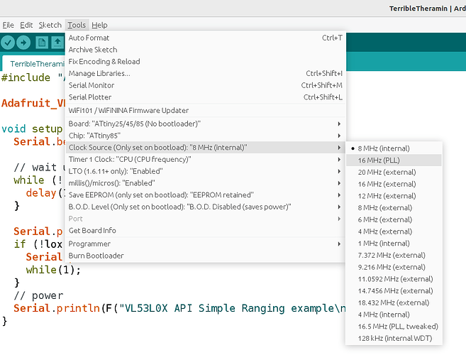
have you tried the 16MHz (PPL) speed? I have never needed it myself, I don't know if it may have any disadvantages over regular internal clock.

Also there is a feature to change the clock for timer 1:


but I think this might cause problems, because:

In your code right now, 32768 interrupts per second occur, from timer 1 overflow. The timer is using the same 8MHz clock frequency as the CPU.

At 8MHz CPU clock, this means only 244 CPU cycles between interrupts. I don't know how many clock cycles your interrupt routine takes to complete. I guess at least 10 cycles per channel, so let's assume 20 to be safe. With 5 channels, that's 100 cycles, plus whatever overhead cycles there are for handling the interrupt. Let's say that's another 20 cycles. So that's 120 cycles in total. That means the interrupt routine is consuming about half of all CPU cycles.

If we use that setting in the screenshot above to increase the timer1 clock to 32MHz, it would generate 128,000 interrupts per second. The CPU is still at 8MHz, so that's only about 61 CPU cycles between interrupts. I think this would result in at least half the interrupts getting missed because they will happen when the CPU is busy processing the previous interrupt.

If you can increase the CPU clock frequency to 16MHz, that would increase the CPU clock cycles to 122 between each interrupt. It might work, but I wouldn't want to take a bet on it!