Good day all.
Have attached the sketch in question for all to review. It is a W.I.P. so it will require a few more refinements.
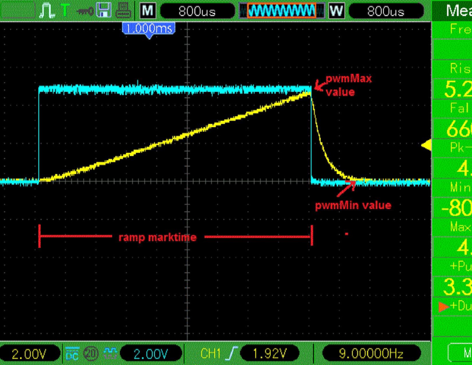
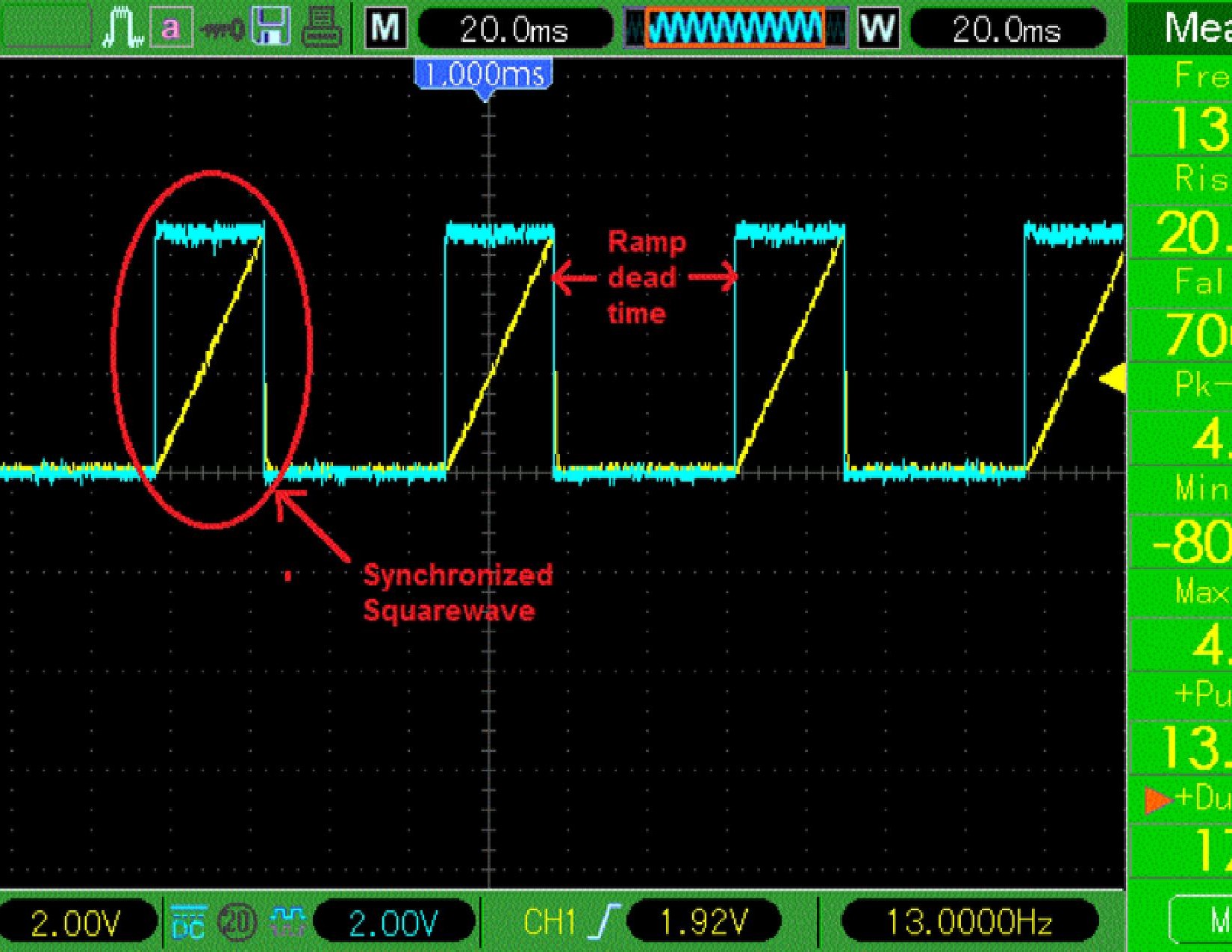
I have attached two 0-scope shots to simplify explaining the waveform construction.
Basically the program should provide a variable length and variable height voltage ramp with of course variable deadtime between successive ramps.
The first issue: When I uncomment the map AnalogRead functions (which are for the variable length, height and deadtime) the Minimum Ramp Marktime (on time) becomes an Order of Magnitude greater.
I require a minimum ramp marktime of about 4ms. This is accomplished by the code until I uncomment the aforementioned functions which then minimum ramp marktime becomes 40ms.
The second issue is that I have substituted variables for the pwmMax function which controls the ramp height and apparently it doesn't.
The main issue is that the program must use a fast pwm clock to make proper use of the low pass filter on the output of the ATTiny85 which is used to refine the pwm output and actually change it into a voltage ramp. At slower (normal) clock speeds the ATTiny85 does not have the resolution necessary to produce a smooth voltage ramp.
Any suggestion as how to put the map AnalogReadfunctions in an ISR would be appreciated.
Thanks
lost_bro
/*
    This Sketch will generate a variable voltage ramp signal
    simultaneous to a syncronized *boxed* square wave.
    //----------------------------------------------------//
    Output: PP 7; P2 of ATTiny85 to a 'Low Pass Filter'
    Values of cap & resistor to be calculated according to
    roll-off frequency appropriate for working PWM freq.

    ARDUINO_ATTiny ---/\/\/\--- | ---- INPUT COMPARATOR
                              |
                             ---
                             ---
                              |
                              |
                            GROUND

   This will produce a *nice* voltage ramp/saw tooth waveform.
   Can be made adjustable by substituting appropriate potentio-
   meter for resistor.
*/
//////////////////////////////////
#define F_CPU 8000000       // This is used by delay.h library
#include <stdlib.h>
#include <util/delay.h>     // Adds delay_ms and delay_us functions
#include <avr/io.h>         // Adds useful constants


/// Define Variables ////

int pwmMin=0;               // minimum pwm voltage (0-255)
int pwmMax=255;             // maximum pwm voltage (0-255)
float ramplength=1;         // us
float INTERVAL=3000;        // the repeat delay interval; us.


/// Define pins for ATTiny85  ///

volatile int outPin = 0;             // PhysicalPin 5; P0
int ledPin = 1;                      // PP 6; P1
int pwmMaxPin = 1;                   // PP 7; P2           Sets Max Ramp hieght.
int ramplengthPin = 2;               // PP 3; P4           Sets Ramp length / Mark Time.
int intervalPin = 3;                 // PP 2; P3           Sets DeadTime inbetween Ramp signals.


///////////////////////////////////////////////////
void setup()
{

    /*
    Control Register A for Timer/Counter-0 (Timer/Counter-0 is configured using two registers: A and B)
    TCCR0A is 8 bits: [COM0A1:COM0A0:COM0B1:COM0B0:unused:unused:WGM01:WGM00]
    2<<COM0A0: sets bits COM0A0 and COM0A1, which (in Fast PWM mode) clears OC0A on compare-match, and sets OC0A at BOTTOM
    2<<COM0B0: sets bits COM0B0 and COM0B1, which (in Fast PWM mode) clears OC0B on compare-match, and sets OC0B at BOTTOM
    3<<WGM00: sets bits WGM00 and WGM01, which (when combined with WGM02 from TCCR0B below) enables Fast PWM mode
    */
    TCCR0A = 2<<COM0A0 | 2<<COM0B0 | 3<<WGM00;

    /*
    Control Register B for Timer/Counter-0 (Timer/Counter-0 is configured using two registers: A and B)
    TCCR0B is 8 bits: [FOC0A:FOC0B:unused:unused:WGM02:CS02:CS01:CS00]
    0<<WGM02: bit WGM02 remains clear, which (when combined with WGM00 and WGM01 from TCCR0A above) enables Fast PWM mode
    1<<CS00: sets bits CS01 (leaving CS01 and CS02 clear), which tells Timer/Counter-0 to not use a prescalar
    */
    TCCR0B = 0<<WGM02 | 1<<CS00;

    /*
    Control Register for Timer/Counter-1 (Timer/Counter-1 is configured with just one register: this one)
    TCCR1 is 8 bits: [CTC1:PWM1A:COM1A1:COM1A0:CS13:CS12:CS11:CS10]
    0<<PWM1A: bit PWM1A remains clear, which prevents Timer/Counter-1 from using pin OC1A (which is shared with OC0B)
    0<<COM1A0: bits COM1A0 and COM1A1 remain clear, which also prevents Timer/Counter-1 from using pin OC1A (see PWM1A above)
    1<<CS10: sets bit CS11 which tells Timer/Counter-1  to not use a prescalar
    */
    TCCR1 = 0<<PWM1A | 0<<COM1A0 | 1<<CS10;

    /*
    General Control Register for Timer/Counter-1 (this is for Timer/Counter-1 and is a poorly named register)
    GTCCR is 8 bits: [TSM:PWM1B:COM1B1:COM1B0:FOC1B:FOC1A:PSR1:PSR0]
    1<<PWM1B: sets bit PWM1B which enables the use of OC1B (since we disabled using OC1A in TCCR1)
    2<<COM1B0: sets bit COM1B1 and leaves COM1B0 clear, which (when in PWM mode) clears OC1B on compare-match, and sets at BOTTOM
    */
    GTCCR = 1<<PWM1B | 2<<COM1B0;

    pinMode(outPin, OUTPUT);
    pinMode(ledPin, OUTPUT);


}


//////////////////////////////////////////////////////////
void loop()
{
static uint32_t StartUs=micros();
static uint32_t StartMs=millis();
static uint8_t Pwm=0;
float  Dir=2.7;


  ////////// pwmMin, pwmMax and interval take an analogRead in for 0 to 1023 as output with 1023 for 5V and 0 for 0V./////


  //INTERVAL = map(analogRead(intervalPin),0,1023,0,30023);                  // adjust all maps according to
  // pwmMax = map(analogRead(pwmMaxPin),0,1023,115,1023);                    // circuit layout & potentiomenters
  //ramplength = map(analogRead(ramplengthPin),0,1023,20000,200000);         // adjust map for packetcount


  ///// Increment/decrement PWM on ledPin with a period of 'x RampLength' in us. /////

  if((micros()-StartUs) >= ramplength)  //12=20ms; 8=14ms; 6=11ms; 5=ms; 1=3ms; OnTime of Ramp;

    {


    ////We arrived here every 'x ramplength' in microseconds////
    StartUs=micros();


        Pwm+=Dir;                                 //increment or decrement PWM depending of sign of Dir

        analogWrite(ledPin, Pwm);                 //Update built-in LED

        if(Pwm==pwmMax) Dir=-1;                   //if PWM reaches the maximum: change direction
        {
        digitalWrite(outPin, HIGH);
        }
        if(Pwm==pwmMin)                           //if PWM reaches the minimum://30=640mv float; 40=840mv float;
        {                                         // delay_ms(40)=36ms; (20)=20ms;
        digitalWrite(outPin, LOW);
        delay(INTERVAL), Dir=+1;                //delay *INTERVAL* & change direction
        }
  }                                               // delay_ms(40)=36ms; (20)=20ms;


}