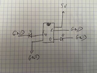
Pour le tester j'alimente l'Attiny85 avec l'arduino en 5V
J'ai connecté une led rouge au PIN 0
et une bleue au PIN 4
Lorsque je connecte l'attiny85, la led rouge s'allume environ 3 secondes et s'éteint.
lorsque je connecte le PIN 2 à la masse, la led bleue d'allume très brièvement et la rouge s'allume pendant 3 secondes.
Je ne m'attendais pas trop à cela comme comportement.
Pour moi lorsque l'Attiny85 reçoit du courant le led rouge doit s'allumer 5 secondes.
Si une interruption apparaît en reliant le PIN2 à la masse, la bleue s'allume 2,5'' et la rouge 5'.
Mais il y a peut être un truc qui m'échappe.
J'ai laissé le code repris dans GitHub tel quel mais dans les commentaires pour l'interruption je pense qu'il faut comprendre PIN2 et pas PIN3.
Merci si vous avez des explications.
#include <avr/interrupt.h>
#include <avr/sleep.h>

//modified from http://playground.arduino.cc/Learning/arduinoSleepCode

int ledPin = 0;            // LED connected to digital pin 0
int interruptPin = 4;      // LED to show the action of a interrupt
int wakePin = 2;            // active LOW, ground this pin momentary to wake up


void setup(){
  pinMode(ledPin, OUTPUT);         // sets the digital pin as output
  pinMode(interruptPin, OUTPUT);   // sets the digital pin as output
  pinMode(wakePin, INPUT);        // sets the digital pin as input
  digitalWrite(wakePin, HIGH);
}


void sleepNow(){

    set_sleep_mode(SLEEP_MODE_PWR_DOWN);   // sleep mode is set here
    sleep_enable();                          // enables the sleep bit in the mcucr register so sleep is possible
    attachInterrupt(0, wakeUpNow, LOW);     // use interrupt 0 (pin 2) and run function wakeUpNow when pin 2 gets LOW
    digitalWrite(ledPin, LOW);

    sleep_mode();                          // here the device is actually put to sleep!!

    sleep_disable();                       // first thing after waking from sleep: disable sleep...
    detachInterrupt(0);                    // disables interrupton pin 3 so the wakeUpNow code will not be executed during normal running time.
    delay(250);                           // wait 2 sec. so humans can notice the interrupt LED to show the interrupt is handled
    digitalWrite (interruptPin, LOW);       // turn off the interrupt LED

}


void wakeUpNow(){        // here the interrupt is handled after wakeup

  //execute code here after wake-up before returning to the loop() function
  // timers and code using timers (serial.print and more...) will not work here.
 digitalWrite(interruptPin, HIGH);
}


void loop(){
  digitalWrite(ledPin, HIGH);            // sets the LED on
  delay(5000);                           // waits for a second
  sleepNow();                      // sleep function called here
}
Il y a quelque chose qui ne va déjà pas dans le câblage, il n'y a pas de résistance en série avec les leds. Cela peut écrouler l'alimentation et faire n'importe quoi.
Si ce sont des leds rouges avec un seuil supposé de 1,5V, il y aurait alors 3,5V aux bornes des résistances qu'il faut mettre en série. Pour un courant de 5mA, il faut donc une résistance de l'ordre de 820Ω
Bonjour, oui effectivement. Du coup j'ai rajouté 1 résistance en série pour chaque led de 680k ( ~ 700k). Mais je constate toujours le même comportement.
Je viens de trouver. En fait je n'avais pas fait un burn boatloader avant. je suis désolé tout fonctionne correctement.
Le programme ci-dessous toujours pris dans github est plus sympa que le premier je trouve pour tester le sleep mode de l'attiny85.
Désolé pour le dérangement
/*
  ATtiny85 sleep mode and wake on pin change
  Author: Davide Gariselli

  Original version made by Nick Gammon https://goo.gl/62b0Im
  // ATMEL ATTINY 25/45/85 / ARDUINO
  //
  //                  +- \/-+
  // Ain0 (D 5) PB5  1|*    |8  Vcc
  // Ain3 (D 3) PB3  2|     |7  PB2 (D 2) Ain1
  // Ain2 (D 4) PB4  3|     |6  PB1 (D 1) pwm1
  //            GND  4|     |5  PB0 (D 0) pwm0
  //                  +-----+

  It's works with 3,3V (8Mhz) or 5V (8Mhz or 16Mhz)
*/

// PinChangeInterrupt ( attachPCINT ) Library 1.2.4 https://goo.gl/WhlCwl
#include <PinChangeInterrupt.h>

#include <avr/sleep.h>    // Sleep Modes https://goo.gl/WJUszs
#include <avr/power.h>    // Power management https://goo.gl/58Vdvv

#define LED 0 // D3
#define SWITCH 2 // D4

void setup () {
  pinMode (LED, OUTPUT);
  pinMode (SWITCH, INPUT_PULLUP); // internal pull-up
  // Valid interrupt modes are: RISING, FALLING or CHANGE
  attachPCINT(digitalPinToPinChangeInterrupt(SWITCH), wakeUpNow, FALLING);
}

void loop () {
  digitalWrite (LED, HIGH);
  delay (2000);
  digitalWrite (LED, LOW);
  delay (2000);
  goToSleep ();
}  // end of loop

void wakeUpNow() {
  // execute code here after wake-up before returning to the loop() function
  // timers and code using timers (serial.print and more...) will not work here.
  // we don't really need to execute any special functions here, since we
  // just want the thing to wake up
}

void goToSleep () {
  //    * The 5 different modes are:
  //     *     SLEEP_MODE_IDLE         -the least power savings
  //     *     SLEEP_MODE_ADC
  //     *     SLEEP_MODE_PWR_SAVE
  //     *     SLEEP_MODE_STANDBY
  //     *     SLEEP_MODE_PWR_DOWN     -the most power savings
  set_sleep_mode(SLEEP_MODE_PWR_DOWN); // <avr/sleep.h>
  ADCSRA = 0;            // turn off ADC
  power_all_disable ();  // power off ADC, Timer 0 and 1, serial interface <avr/power.h>
  sleep_enable(); // <avr/sleep.h>
  sleep_cpu(); // <avr/sleep.h>
  //---------------  THE PROGRAM CONTINUES FROM HERE AFTER WAKING UP ---------------
  sleep_disable();// <avr/sleep.h>
  power_all_enable();    // power everything back on <avr/power.h>
}