I'm actually trying to identify the cables with the rings on the connector with a continuity test with a multimeter but i can't get any of the four wires to show continuity on any of the rings. Why?
The shields are most-likely connected together at the other end, where presumably there is a 3.5mm TRS connector. In that case, you can connect the two shields together (and to ground) or you can ignore one.
Do you have a multimeter to "Ohm-out" the connections?
There are 2-conductor "mono" TS connectors, 3-conductor "stereo" TRS connectors, and 4-conductor TRRS connectors for a stereo headset plus a microphone.
...Your phono looks like two separate cables so it's impossible to know what you've got.
Will I be able to use this in my CT current sensor?
So you're suggesting I test with ohmage instead of continuity?
Yes. that's the usual way, unless you have some kind of continuity tester.
A "direct connection" (or a "short") will read zero Ohms (with some allowance for resistance in the meter leads, wires, and connections, and some tolerance in the reading... so it wouldn't be unusual to read 1 Ohm or so).
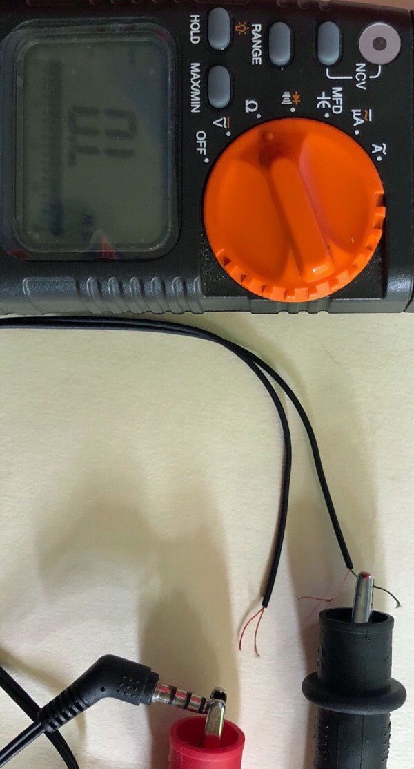
But there is no continuity beep and there is always OL ohms, so I must be doing something wrong.
A broken cable isn't unheard-of, but ALL of the connections shouldn't be broken.
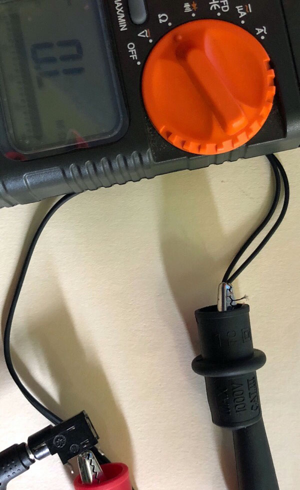
I wonder if it's that "funny" enamel-coated (insulated) wire? Try measuring a short-distance on one of those shield wires to see if the meter probes are making contact with the copper.
If that's the case, you can scrape-off the enamel but you usually end-up breaking some of the strands and it's still very-difficult to solder. So, you might want to try a different cable or buy a plug and make your own cable.
You have a TRRS plug (4-conductors) but the your jack appears to be 3-conductors. Or, you could have 2 ground connections on the jack, or maybe I'm seeing it wrong. They should work together but of course you won't get all of the connections.
It's not unusual for the microphone and headphone wires to have separate shields. But, there should be 3 signal-wires plus the shield(s).
The shields should be connected together at the connector(s). The colors aren't helpful (before you test/measure) because nobody cares about the colors inside the cable (unless you bought a single-ended cable that came with specs.)
DVDdoug: I wonder if it's that "funny" enamel-coated (insulated) wire? Try measuring a short-distance on one of those shield wires to see if the meter probes are making contact with the copper.
If that's the case, you can scrape-off the enamel but you usually end-up breaking some of the strands and it's still very-difficult to solder. So, you might want to try a different cable or buy a plug and make your own cable.
I would put money on this being the case. See how one of the wires in each pair is coloured but still looks metallic? There also doesn't appear to be any plastic insulation between the two wires of each sleeve.
DVDdoug:
A broken cable isn't unheard-of, but ALL of the connections shouldn't be broken.]
But a yanked cable can snap all the conductors - the insulation is much stretchier and often
won't show damage externally. I've seen audio cables with 3 or 4 breaks along the length in fact,
took quite a while figuring that out (divide and conquer with snippers!!), though to be fair the braiding
survived in that one.
Remember there are clowns that lift equipment by its cables, and its not unusual for dangling cables
to be walked into, both can wreak havoc.
That depends on what your power sensor needs. A CT is two wires, but you might want to ground
the screen at the Arduino end only to reduce noise pickup.