Hi everyone, this is my first forum post!
I have successfully reproduced this project that I found online: The Yeah! Woo! machine
(Im only using one Atmega not two like in the project)
My next objective for my project is to add another speaker that produces a tone, using the tone() function to play some simple melody over the top of the sample. One of the caveats of this function is that it breaks PWM on pin 11 and 3.
The existing project uses pin 11 as its main output. Here is the main code body that this topic is concerned with: PCM/PCM.c at master · damellis/PCM · GitHub
void startPlayback(unsigned char const *data, int length)
{
sounddata_data = data;
sounddata_length = length;
pinMode(speakerPin, OUTPUT);
// Set up Timer 2 to do pulse width modulation on the speaker
// pin.
// Use internal clock (datasheet p.160)
ASSR &= ~(_BV(EXCLK) | _BV(AS2));
// Set fast PWM mode (p.157)
TCCR2A |= _BV(WGM21) | _BV(WGM20);
TCCR2B &= ~_BV(WGM22);
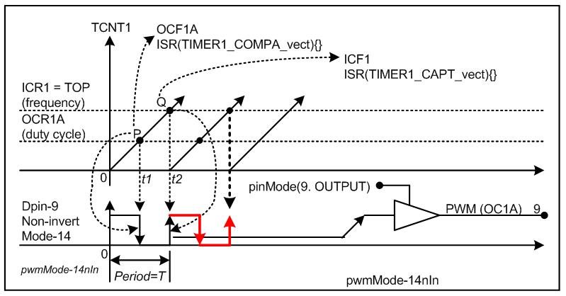
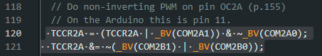
// Do non-inverting PWM on pin OC2A (p.155)
// On the Arduino this is pin 11.
TCCR2A = (TCCR2A | _BV(COM2A1)) & ~_BV(COM2A0);
TCCR2A &= ~(_BV(COM2B1) | _BV(COM2B0));
// No prescaler (p.158)
TCCR2B = (TCCR2B & ~(_BV(CS12) | _BV(CS11))) | _BV(CS10);
// Set initial pulse width to the first sample.
OCR2A = pgm_read_byte(&sounddata_data[0]);
// Set up Timer 1 to send a sample every interrupt.
cli();
// Set CTC mode (Clear Timer on Compare Match) (p.133)
// Have to set OCR1A *after*, otherwise it gets reset to 0!
TCCR1B = (TCCR1B & ~_BV(WGM13)) | _BV(WGM12);
TCCR1A = TCCR1A & ~(_BV(WGM11) | _BV(WGM10));
// No prescaler (p.134)
TCCR1B = (TCCR1B & ~(_BV(CS12) | _BV(CS11))) | _BV(CS10);
// Set the compare register (OCR1A).
// OCR1A is a 16-bit register, so we have to do this with
// interrupts disabled to be safe.
OCR1A = F_CPU / SAMPLE_RATE; // 16e6 / 8000 = 2000
// Enable interrupt when TCNT1 == OCR1A (p.136)
TIMSK1 |= _BV(OCIE1A);
lastSample = pgm_read_byte(&sounddata_data[sounddata_length-1]);
sample = 0;
sei();
}
void stopPlayback()
{
// Disable playback per-sample interrupt.
TIMSK1 &= ~_BV(OCIE1A);
// Disable the per-sample timer completely.
TCCR1B &= ~_BV(CS10);
// Disable the PWM timer.
TCCR2B &= ~_BV(CS10);
digitalWrite(speakerPin, LOW);
}
What I would like to do is change pin 11 in the register to any other PWM pin except from pin 3, which is also broken by the tone function.
In the notes you can see that pin 0C2A is pin 11. I would like to change this to a different pin so when i use the tone function it doesnt break the sample playback.
Im not sure if this is even possible, as to be honest I was only introduced to the concept of registers 2 days ago. So apologies if this is in the wrong place.
Cheers!