Hi. I'm not new to Arduino but I have a project in mind that I don't know how to approach. I have a guitar pedal (Boss SY-1) that can make a "wah wah" sound when I connect an expression pedal with a 6.3 mm TRS (tip ring sleeve) stereo cable (Roland EV-5) to it. I understand that the expression pedal is basically a potentiometer. Instead of that expression pedal, I want to use an Arduino to "open" and "close" the expression pedal in a sine curve with the tempo (time between "open" and "close") being defined either in the code or maybe later with a potentiometer.
I have measured the resistance of the Roland EV-5 expression pedal at the TRS jack :
0 Ohm (closed) to 10.5 kOhm (open) between the ring and the tip,
0 Ohm (open) to 10.5 kOhm (closed) between sleeve and tip, and
10.5 kOhm between sleeve and ring (open and closed).
For these measurements, I had the dial on the side at 0 (it can be rotated from 0 to 10, see schematic, below).
I have also measured the voltage coming out of the Boss SY-1 guitar pedal at the female TRS jack for the expression pedal:
2.25 V between sleeve and tip, and
3.30 V between sleeve and ring.
Can anyone tell me to which of these contacts I would have to connect the Arduino and what voltage I would have to send for an "open" or "closed" expression pedal?
The next question would be how I specify the sine function to "open" and "close" the expression signal in a pre-defined tempo.
I would not connect it straight to the arduino for a few reasons. First of all, an Arduino can create a PWM signal, but that is not the same as a constant voltage, you would have to filter the signal.
Secondly, the pin on the pedal that is taking the variable input is connected to something ? but what.
I would try to use a PNP Transistor like a BC557 and control it through a filtered PWM output. What you want is a variable resistor, and that can be simulated like that. Also using a PNP will keep the dial functioning.
Just thinking that instead of a transistor, you could also try an opto-coupler and filter with a capacitor.
Without the schematic of the f/x pedal, it is impossible to know the roll the variable resistance is playing in the circuit.
It could be delivering a control voltage, in which case measuring and simulating would work, if you used a real digital to analog converter, either by using a microprocessor that has one, or an external d/a chip or module.
When you say
I have measured the resistance of the Roland EV-5 expression pedal at the TRS jack :
do you mean at the plug? Did you measure resistance in an active circuit? Let's say you were actually measuring the resistances made by the pedal… but that resistance might only be part of some analog circuit - so just making a voltage isn't gonna work.
In audio it is not uncommon to use an LDR, light dependent resistor, usually a CDS cell, not a photocell or a phototransistor.
If you found one that varied with approx. the same range as you real pedal, then you could use that and make your adjustment by modulating a tightly coupled light source, a small incandescent bulb in the old days.
The code would then illuminate the bulb from dim to bright, again you'd need a real d/a, even an incandescent bulb would not filter the PWM which is fake analog. An LED would bring the PWM through very too well.
The code for doing the things you want is fairly simple, where are you on the learning curve? This is a matter of timing and looping and buttons, first things to learn about. Hooking up an d/a module is a bit more to chew on, but no large deal given our friend google and your new friends here to help.
The big big problem with the light dependant device and a light source is that it would not be linear.
That is very very true.
However I would be inclined to use two digital pots to emulate these two resistors. However as noted your success would depend on the actual voltages and polarities at the peddle end. You might have to use an digital pot that requires a negative voltage reference supply.
Thanks for your answers. The resistance of the Roland EV-5, I have measured when it was not connected to anything.
There is no audio exchanged between the Boss Sy-1 and the Roland EV-5. Such volume or expression pedals are usually simply variable resistors like potentiometers. Therefore, it should not be necessary to use light dependent resistors / photocells in my opinion. There are many many guitar pedals that are compatible with standard 10k expression pedals like the Roland EV-5 but I couldn't find a schematic right now. I will keep searching if it helps to solve my problem.
Is there no possibility for the Arduino to mimic what a potentiometer does? I mean to allow a current to flow through but to have a variable resistance that I can control from the Arduino? To me it sounds like that would be the easiest solution.
I have done many things with my Arduino in the past like control motors with a brightness sensor, convert data in to MIDI, connect and use other input and output elements (buttons, faders, potentiometers, LEDs, relays, small graphic displays...), so the actual coding I'm actually looking forward to as soon as I understand what needs to be done.
OK, but that does not mean that a given f/x pedal is using it in any kind of standard way. An f/x designer may exploit whaat s/he knows to be the schematic of the pedal, in any number of ways - not just providing a voltage.
Not without external circuitry. I think all the ways you could add to an Arduino to do that have been revealed here.
The closest to what you think might exist on board is a digital potentiometer, and as far as I know there are no microprocessors or convenience boards built around them that have that capability build in.
And that, as the discussion has pointed out, may not be a satisfactory solution.
If you are the kind who might, some experimentation would answer questions. I'd wait to see, however, just how the pedal is used by any f/x device you wish to control.
The main disadvantage of potentiometers is that they wear out and are moisture sensitive, That is why for instance my behringer uses a LED a variable transparent piece of plastic and a photo-transistor to determine how far the pedal goes down. That is not an uncommon method. Still it should be all that relevant and it probably does just have a potentiometer. Open it up and find out I think you can manage to get control using some basic parts, but a digital-potentiometer would simplify things though.
which seems to suggest that you could indeed use a regular digital to analog converter to create a voltage and directly control the pedal:
Yes, control voltages work with the expression pedal input. Our pedals expect a voltage of 0-3.3V on the tip (sleeve grounded), but voltages outside that range should not cause damage. In most cases you will need to use a CV attenuator (a passive voltage divider will work).
So maybe stick with the digipots, but know you could use a different method. It would still need a d/a module or low pass filtering and perhaps amplification of the Arduino fake d/a PWM output.
I have no idea which would be better, nor on what criteria to choose. A real d/a would give much greater resolution, it may not matter.
If you are in with the ppl at mission perhaps they would be in a position to advise.
I find SPI to be easier than I2C to work with, so when there is a choice, that is what I choose. If I was using digipots. Or real digital to analog converters for that matter.
From the software point of view it makes no difference. You will be creating the time varying number of whatever range is needed and using that at the lower level to make either the resistance or voltage be what it should.
Thanks a lot for your post. I have already ordered an MCP41010 digital potentiometer with 10K Ohm, so I'll go that pathway for now, "emulating" the function of a manual potentiometer with the Arduino.
Also, I think it's safer to do that than play around with voltages, risking to fry my Boss SY-1 pedal
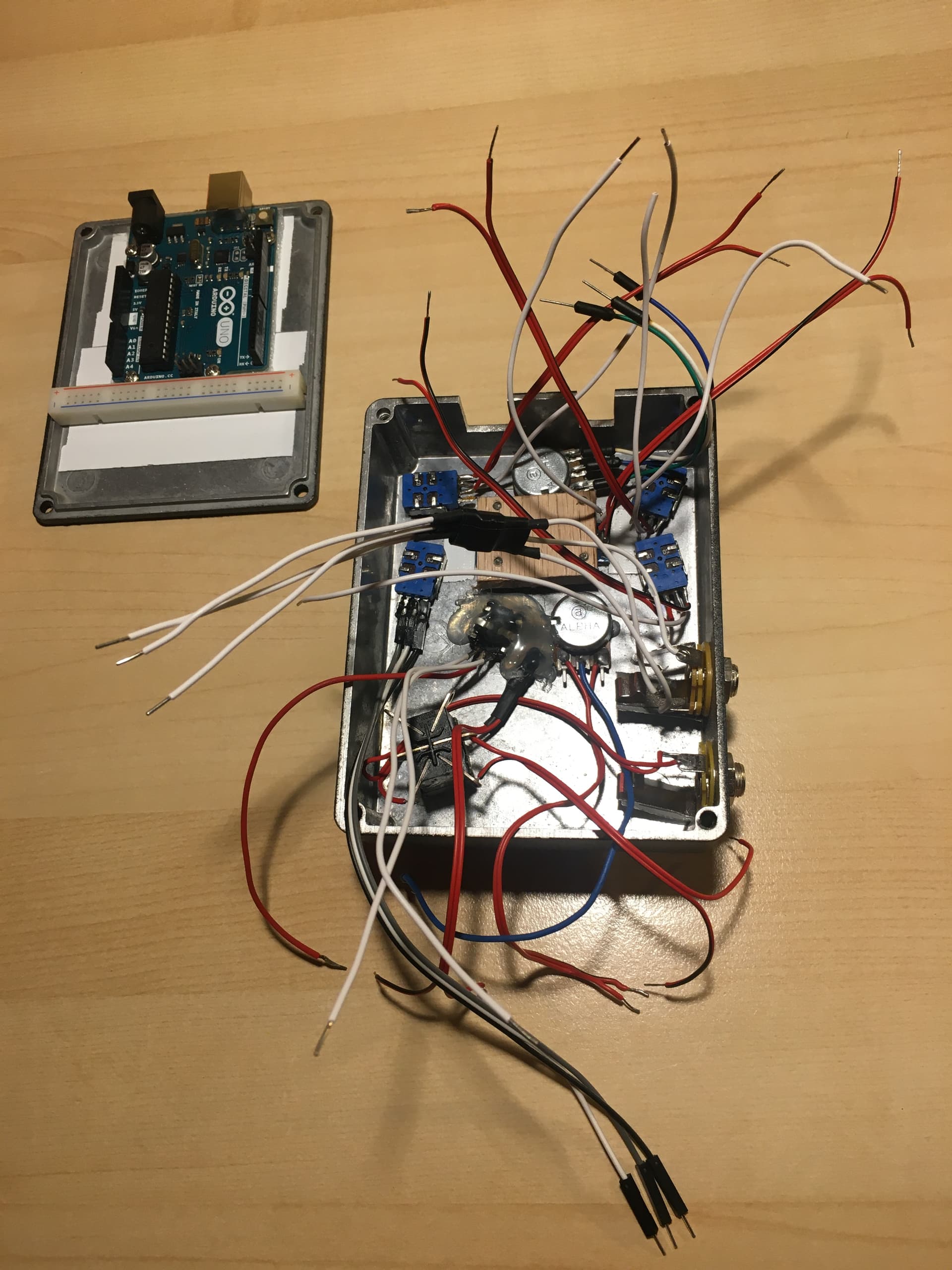
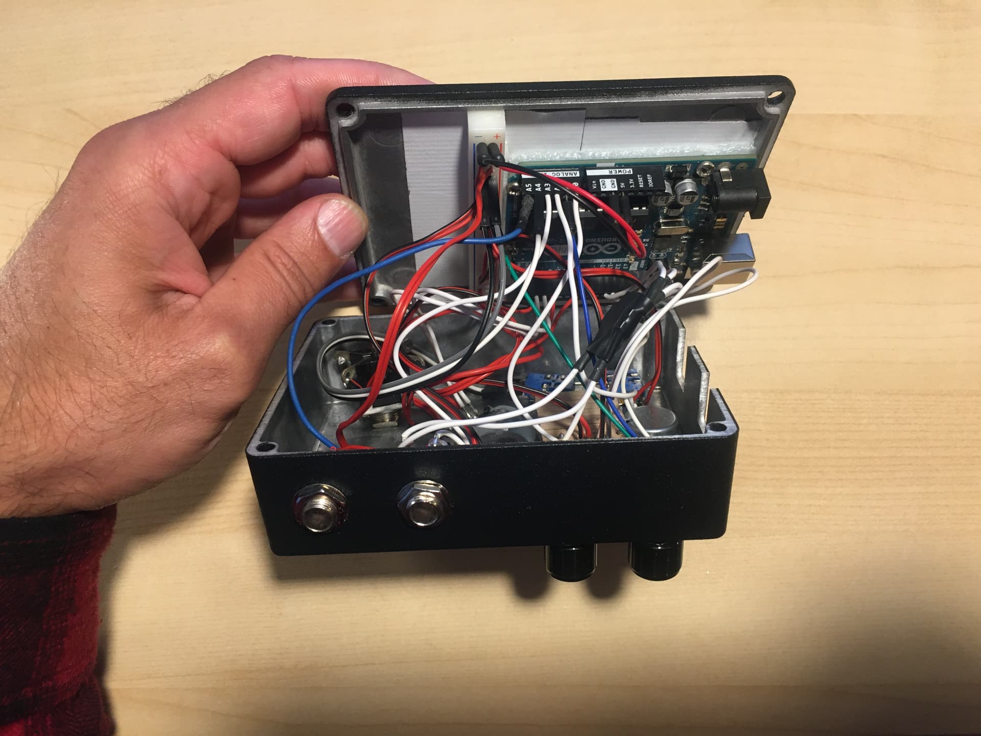
A quick update on this: It's going really well. I figured out how to control the digital potentiometer to give the correct signal to my effect pedal. I even like the visual appearance of the whole thing.
However, I am running into a problem now that is unrelated to the digital potentiometer and which has just to do with using 6 analog potentiometers at the Arduino Uno's 6 analog inputs. But, since it is unrelated, I have opened another topic for it: Six potentiometers and a display = arduino crashes