Adding MIDI to a Tech21 SansAmp Pedal
I recently completed a project where I added MIDI preset recall capability to a guitar effects pedal, and thought I’d do a write up so others may benefit from it.
First off, I have to give a big THANK YOU to both allanhurst and Grumpy_Mike. These two guys were extremely helpful, and certainly instrumental in the success of this project.
The full details on the project are located here: Virtual, variable resistors, with saved presets recallable by MIDI - General Electronics - Arduino Forum although I thought a more organized write up would be helpful to future searchers looking to do something similar.
My goal was to add MIDI preset functionality (ie: saving and recalling presets by MIDI) to a Tech21 SansAmp British effects pedal. This pedal is designed to emulate an amplifier, for use in running a guitar pedal board direct to a PA.
Here is the pedal I modified:


And here’s a look at the end result:

On the left side of the pedal, the ¼ output and power cables are original, but I added the 1/8” jack at the top for the MIDI input signal.
On the ride side, the ¼” input cable is original, but I added the RJ45 jack, and also (what you can’t see in the picture), I cut a hole so the USB port of the Arduino can be accessed without opening up the pedal.
These are the essential main parts of this project:
-
Arduino for interfacing and running the program
-
I used an Adruino Nano
-
Analog potentiometers (POTs) for user input
-
I planned to use the existing POTs, but needed to replace them due to damage. I used 100k linear POTs, as that's what was in the pedal
-
Digital potentiometers (Digi-POTs) for interfacing with the pedal’s electronics
-
I used some MCP41100 ICs for this
-
An opticoupler for interfacing with the MIDI network
-
I used a 4N35 which came with this Arduino breadboard kit
-
Power source for powering the Arduino and added components
-
I ended up needing to build a power supply to keep everything noise free
-
LCD display and a rotary encoder for navigating, storing, and recalling presets
-
I used this Rotary Encoder, which has a push button built in, for preset navigation, saving and storing.
-
I used an Adafruit 4 Character, 7-Segment Display with I2C Backpack, for the display. I opted for blue, but there are other colors available.
-
And I used this project box to house the rotary encoder and display; since the SansAmp pedal enclosure isn’t large enough to house everything.
I wanted the pedal to be functional without anything external connected, so I needed to fit the Arduino, the Digi-POTs, the Opticoupler, and power supply all inside the SansAmp pedal’s enclosure.
I used prototype boards from This Kit to create boards to install inside the enclosure.
Main Arduino Board
Here is the 1st board with the Arduino, the Digi-POTs, the opticoupler, a diode, and some resistors all mounted.

The 6 wires on the left side are the Digi-POTs outputs, and you can see the 1/8” jack for MIDI input under those wires, if you look closely.
The wiring is all on the underside of the board:

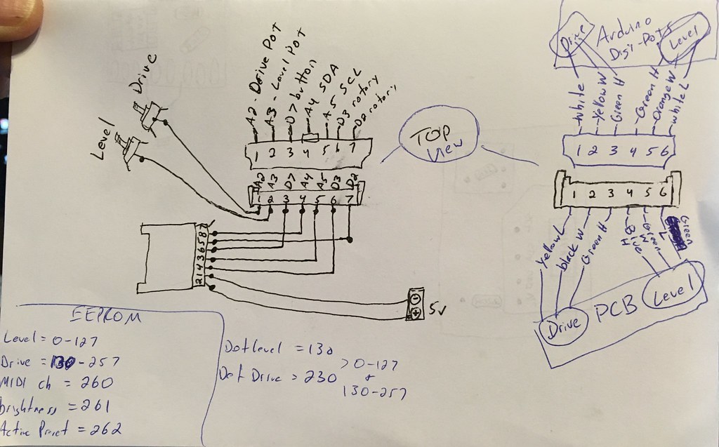
And here is how the components are connected:
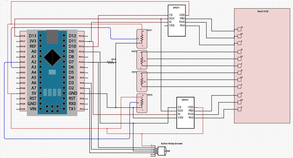
The Digi-POTs follow the above connection points. Notice the 4 analog POTs in the diagram. These relate to the LEVEL, MID, CHARACTER, and DRIVE knobs on the pedal. I only added preset capability over the LEVEL and DRIVE knobs though; but left all 4 in the diagram for a more complete understanding of how it’s all wired up.
So you’ll notice the 1st and last POTs are connected to the arduino, while the middle two continue to connect to the pedal, since I didn’t change those.
And here is how the Opticoupler is wired on the board.
(Image taken from this InvisibleCraftsLabs Instructable)
I added a 1/8” jack for the MIDI input, instead of using a 5 pin DIN connector. I did this due to space constraints, and since only 2 wires are needed for MIDI input, it made sense. If you want to do MIDI in, out and/or through … then you’ll need more wires and possibly the 5 pin DIN connector.
Power Supply Board
For the power, I didn’t want to add an additional power connection to the pedal, and wanted to tap into the existing 9v supply the pedal uses. I tried powering the Arduino and the other added components several different ways, of which all resulted in extreme noise on the guitar’s audio signal when it passed through the pedal. Allan (referenced above) helped greatly with this, and designed this power supply for me:

And here it is, worked up on the 2nd prototype board for installation inside the pedal’s enclosure:

Essentially, this power supply steps the voltage down from 9v to 5v, by shifting the positive side by 2v and also shifting the negative side by 2v, landing at 5v but keeping it centered around the 9v supply. Doing it this way completely eliminated the noise on the guitar signal, and allowed me to tap into the existing 9v supply inside the pedal.
Here is a look at the power supply laid out on a breadboard, just because it makes it easier to see how everything is connected. I did add a 100uf capacitor to the design (based on recommendation from Allan) to further protect against noise on the power bus.

Since the TLC2262/2 opamp is dual channel, only one is needed here. One channel is used for the positive side and the 2nd channel is used for the negative/ground side.
Breakout Box
For user control of the presets, and adding the display … I opted to create a small breakout box and used a network cable to connect it to the SansAmp pedal.
I used another prototype board to mount the rotary encoder and display onto, then mounted that board inside the project box. I also added the RJ45 jack to it, for connecting to the pedal.
EDIT: Since writing this, I've created a short sketch to seed EEPROM data to an Arduino. I've also added other functionality which can be read about below. Find the latest .ino version further down in this thread
I've added another attachment to this post, "eeprom_seed.ino", which when run, will seed the EEPROM of an Arduino with the appropriate data for preparing it for the MIDI Control Sketch.
SansAmp_MIDI_Control_v5.ino (24.3 KB)
eeprom_seed.ino (2.93 KB)