I am trying to make my own board, ive already made one with the atmega328p-pu and now one with the atemga328p-mu. I get like the error:
avrdude: Device signature = 0x000000
avrdude: Yikes! Invalid device signature.
Double check connections and try again, or use -F to override
this check.
when using a other arduino as the isp programmer and im using the following pinout as the programmer setup:
master slave
10 RST
11 11
12 12
13 13
5V 5V
GND GND
This signature, or 0xFFFFFF, indicates something isn't connected properly with the ICSP wires between programmer and the ATMEGA. The programmer is trying to read the signature and getting either all zeros or all ones, no data.
i now added some headers and got:
avrdude: Device signature = 0xffffff (probably .avr8x_mega)
avrdude: Yikes! Invalid device signature.
Double check connections and try again, or use -F to override
this check.
There you go. Adding the headers should have made no difference, yes? Unless the programmer's input (MISO) is floating. Then it can read ones or zeros at random.
I am not the best at reading datasheets especially when they are that long. For the headers I first just put some headers in the holes and not inside actual headers.
And where do you mean a bypass cap, yes I am missing one between AREF and GND but that is only for the ADCs right?
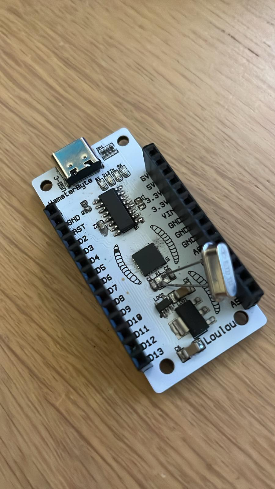
This is the board, don't look at the clock i used a smd one but apparently it is a oscillator and not a crystal and these where to only ones i had laying around!
Okay so back to it, apparently there was a short between GND and RST and after fixing it it works perfectly, only thing is that the RX and TX lights are always on and the 5V led turn instantly off after boot and the D13 led doesn't blink (i uploaded blink code and the pin 13 with a oscilloscope it turns on and off but not the led?)
Check if the LED and the resistor in series are connected properly - PWR and D13 LED.
In case of Rx and Tx it seems weird as you wrote it is able to upload and they are directly connected to the Rx and Tx lines.
Okay so i looked at it and all the GNDs of the 4 leds are connected in paralle and D13 is connected to pin 13 which does turn on and off and the 5v is directly to 5V the usb and the power convert circuit. And with tx and rx how can i can connect them like a arduino? The arduino uses a other usb to serial where they can do it but since i use the ch340c i dont have a sepperate tx rx pins for that?
Tx and Rx LEDs should be connected directly to the appropriate lines. In case of CH340 there is no other option. However, it is weird to me they are always on, since there have to be signal 0/1 during the upload.
5V an D13 should not be so hard to investigate it. In case of 5V diode, must be 5V on the anode and about 2V drop on the cathode, e.g. check if they are oriented correctly.
Yes like they are always on even when inactive or powered not even from usb. and there is a voltage drop of 2 volts over the 5V let because of the 5.1kohm and then RX is fully on and the tx barely for some reason. Also the 5V does turn on when boot and after like 0.5 seconds it turns off and the tx rx lets turn on and nothing else after that
No shorts, checked every trace that even connects to those leds, and i know the 5v works because on boots it turns on for like 0.5 seconds before the tx and rx get a chance. I also looked at it with a bench psu and still the same
You have one resistor for all the LED. That only works if all the LED Vfs are very close but in your case the one with the lowest Vf will turn on first and cause a large voltage drop across the common resistor preventing the others from turning on.
Added to what jim-p has just said, you are using LEDs of different colours (orange, green and blue) so there will definitely be different forward voltages across them.