Just a hobby guy when it comes to PCB creation....
In the past... I have created board that have a +5v regulator.. that also feeds into a +3.3 regulator..etc..
My current project has both an SMD +5v regulator.. and a +3.3v SMD regulator that is fed from the +5v regulator.
These are SMD regulators.. and do not provide/allow a lot of current..
Is it bad practice to add -another- +5v regulator (fed from the V+ input directly.. not connected to any other regulator on-board)??? Or should I just try to swap out my current SMD +5v regulator for a more robust one that allows more current? (LM7805 or something?)
Not asking HOW to do this in EAGLE.. just talking best practice? or what is acceptable over the other?
You can go series or parallel depending on which way makes sense in your application.
In series, the first regulator has to handle all of the current (so it gets hotter than parallel) and in parallel the low-voltage regulator has to drop all of the voltage so it get's hotter than series.
The Arduino Uno has the 5V & 3.3V regulators in series.
"By default" or at low current, I'd generally go with parallel.
We've got a board at work that's powered from 5V but there are 3.3V circuits, and the CPU runs at 1.8V. The 5V isn't regulated and the 3.3 & 1.8V regulators are in parallel, both running from 5V.
A long time ago, I remember seeing an audio preamp circuit with series regulators to improve the "noise filtering" capability of the regulators.
It's a bad idea to put two regulators in parallel, that is, have the regulators' Vin connected to each other and 5V outputs connected to each other because the regulators may not share the current evenly.
One can have two regulators if 5V output networks are isolated. This is commonly done to isolate two sub-circuits, for instance one might have a separate regulator for analog circuitry and digital circuitry to mitigate getting digital switching noise on the analog power.
For a purely digital circuit one would typically use a single higher rated component.
I dont think use a buck is in option in this case.. as I'm designing the PCB and it all 'has to be on-board' (so to speak)..
Further details in case it changes anyones stance/feedback..
My current custom (all-in-one) board is basically an Arduino and Adafruit 'Waveshield' all merged into one.
I have done this before with other custom boards I have made.. and it works great.
It currently has a +5v regulator (SMD).. dont recall part# or current limits..but if I recall.. roughly 150mA or something?
it also has a +3.3v regulator.. (fed from the +5v regulator)..
For the uSD card/buffer...etc..etc...
However... on this project, I am also adding in some 5050 packaged LEDS...
My choices were/are:
Neopixels or add in an MAX7219 chip..
Pros & Cons *(as I see them)
- Neopixel approach:
+5v
no extra IC's required
lots of CPU required (plus waveshield stuff)
Neopixel set-up not tested with Waveshield requirements (might be idea killer)
- MAX72219 approach:
easy control over many leds
+5v requirement
current needs are low due to multiplexing of MAX7219 chip
No RGB like Neopixels
extra IC integration on PCB
extra routing of 'matrix' led wiring (might be idea killer)
In my mind.. the current regulators.. are -not enough- to power anything more than what I have going on.. so if I add Neopixels or the MAX7219 chip.... I was thinking adding -another- +5v regulator.. to power the MAX7219 chip (or the Neopixels)..
-OR-
Use a bigger regulator (like a LM7805 or equivalent) that supplies 1A or 2A
I'm at the point where I need to add in the '5050's' of my choice.. and any extra needed components (regulator, limiting resistor, decoupling caps..etc)
xl97:
I don't think use a buck is in option in this case.. as I'm designing the PCB and it all 'has to be on-board' (so to speak)..
That is simply a nonsensical suggestion.
If a "buck" regulator is what you need for the purpose, then that is exactly what you need to place on your PCB. larryd has illustrated a number of those readily available in modular form, designed specifically to be mounted as "daughterboards" on your own PCB.
It is not worth your time to attempt to replicate the sophisticated design of switchmode regulator PCBs, or indeed, to source the individual parts. And it would be foolish to use a poorer form of regulator which will take up more PCB space to allow for the heatsinking and reduce reliability due to increased operating temperature of the whole design.
These are simply functional modules. An ATmega328 is a functional module. You build something by putting functional modules together. It is mostly a waste of time and effort replicating the various parts of an Arduino when a Pro Mini can be used, mounted as a functional module.
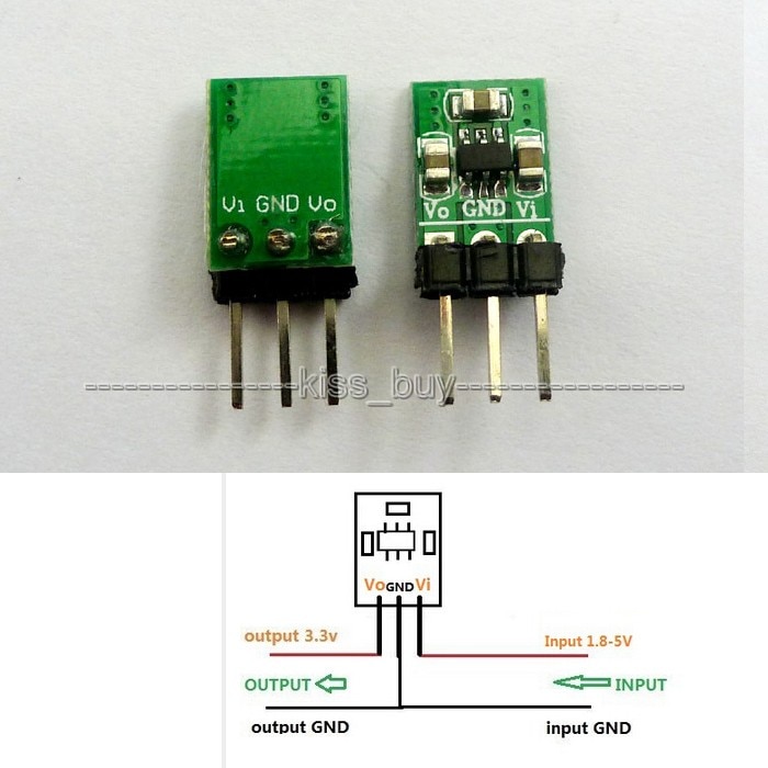
it looks as if there are only '3' components to it? Thats it?
Could I just incorporate those 3 components into my board?.. replacing the SMD +5v regulator I am currently using?
If supplied with more than +3v (according to the listing specs)..
"Input Voltage:>3V;output voltage 5V;current 380-480mA"
This should be enough current for my needs..
this could then power the current +3.3v regulator.. and I wouldnt need to worry about a '2nd' +5v regulator to power the MAX chip (or neopixels if I go that route, which is looking doubtful)
Or am I missing/overlooking something? Or not heeding to advice from above in some form?
"Point-of-load" regulation is absolutely the standard way to do things, complex boards can have dozens of regulators scattered about, no exageration. Then each part of the system gets the voltage, current and accuracy / low noise supply it wants without interfering with any other part of the system.
At low voltage you both lose voltage and board area if you distribute supplies post-regulation all over the board.
The pre-regulator supply traces can be much thinner as you don't care about the few 10's/100's of mV of drop across them, and you don't mind them picking up noise from other parts of the board either as the regulators will deal with that.
Its very common to see ADCs and DACs with two supplies, one clean for analog (high performance linear regulator), one dirty for digital (often switch-mode shared with the microcontroller/whatever)
When deriving 3.3V from 5V its important to use a low drop-out (LDO) regulator - a common one is the AP1117-33.
My current space is at a premium unfortunately.. and if I could just add in these 4 SMD components and replace my current +5v regulator.. it would be a good match/solution for me.
I understand the argument about 're-inventing' the wheel.. especially for more intricate/detailed boards..
I have added on Nano/Pro-MIni, DFPlayers, and other boards as-is (aka: as daughter boards).. so I'm not opposed to it in general.
Just in this situation, where space is limited.. and its ONLY 4 components.... I'm not really see a valid argument to NOT just add in the components?
Looking at the datasheet..
is that:
The LM3671 chip
4.7uF cap (IN)
10uF cap (out)
and.....?
what is that L1:2.2uH part?
any concerns with going this route and playing audio?
My current board: (my all-in-one compared to an Uno and its Waveshield)
that just has 2 LDO regulators (+5/+3.3v) works fine... audio is fine..etc..
I'm tryign to extend this design to add in MAX7219 (or Neopixels)... so I wanted to address having enough power.. but not clear if this will have any negative effect on audio? (I read things about noise..and power supplies, regarding audio...so I figured I'd bring it up?)
I'll order some of these LM3671 chips soon to play with. (maybe they also have a breadboard friendly one as well)
I believe both are available in 1206 footprint.. which I can work with (most other components are 0603)
Thoughts?
Update:
Actually.. I just realized I have been looking at the wrong schematic this whole time?
Been looking at and talking about the +3.3v version?.. (right).. but in my head I have been thinking the +5v version.. because that is what I would need. that page has some many images! LOL
ODD?.. lol.. I used the thread tools to post the links..
They are accurate, just need to copy and paste I guess?
Anyways.. form the ebay link/auction..
I see these two as the +5v versions?
Questions for you pros: :)
Why are there '2' versions of a +5v board?
** (see attachment)
Looks like one board has:
'coil' (inductor?)
and a part that has:
"SS14" on it?
The other board:
2 x passive components
&
an IC that has:
218A
1549/50
on it?
I'd rather just get these tiny and few parts.. and follow suit? Anyone help on the parts they used? (or why one board/approach would be than the other?)
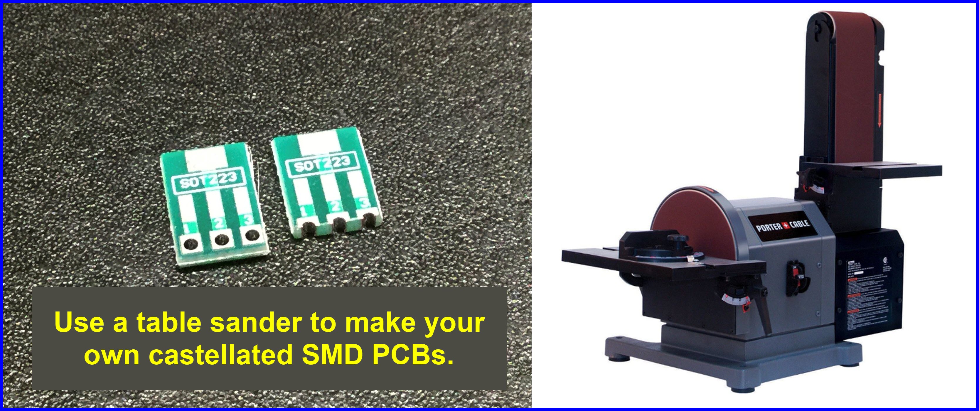
@larryd
I like the sander trick! I could use my mill too.. but the sander would be so much faster!
I'm gonna remember this the next time I'm going to 'daughter-board' one my pro-minis laying around (much better than using through hole headers all the time)