The purpose of a resistor is to limit current - not voltage.
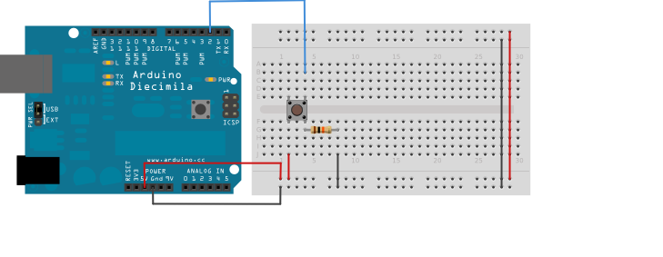
In this case, we have a momentary button - these buttons have their "contacts" connect via opposite corners of the device. So - for the same side of the device, both pins are electrically connected. Thus, those on the right hand side are connected together, and those on the left hand side are also connected together - but the left and right sides are electrically seperated - aka "open" - until the button is pressed - aka "shorted".
So - with that in mind, you can see that the digital pin 2 goes to the right side of the button, and that the resistor on that same side is connected, and then the other side of that resistor is connected to ground. This is called a "pull-down" resistor configuration; it's purpose is to ensure that the digital pin is kept LOW when the button isn't pressed (otherwise, the pin is in a state known as "floating" - which is an indeterminate state, and could be affected by the environment - causing it to be HIGH randomly - the resistor to ground prevents this).
Now - you have asked "Can't I just leave the resistor off?" - Well, if all you wanted to do was to keep a pin at a LOW state all the time, that would certainly be possible (provided you never told the pin to be an output and drive it HIGH - which would then dump a bunch of current - unlimited by a resistor! - and burn the pin out)...
But we have another possibility here: What happens when you press the switch?
Well - you have 5V coming from the Arduino, going to the switch - which is now closed - and what if that resistor wasn't there?
Well - the current would take the path of least resistance (!) and go straight to ground - effectively shorting your power supply (the source of the 5V) and likely burning out the regulator (or catching the switch or wires on fire, or both - but in the case of the Arduino's voltage regulator, it would likely just cause the Arduino to reset - or the polyfuse to blow).
That resistor is there to prevent this in the situation that the switch is pressed (and the contacts closed) - so that the digital line on Pin 2 of the Arduino will be raised HIGH (some current will also flow to ground - but not much).
Thanks a lot~ that clears up so many questions
two more questions though,
If I understand it correctly, even with resistor, current will still flow to the ground, that means there's small amount of short-circuiting happening.
In arduino's case, how much current flow through the gnd pin without damaging the hardware?
Pull up resistors are very crucial part of microcontrollers. Well, most replies to the post has explained well but otherwise resistors serve the process of limiting current to the LEDs.As you may know the LED's take about 40mA of current to glow.
I concur... always assume a standard red or green unmarked/unknown LED will only need about 10-20 mA for ample brightness. 40mA will exceed the max rating of many LED's.
Some LEDs will tolerate 35-40mA if they are pulsed on, datasheet for the LED will have a note like this:
"Peak Forward Current (1/10th duty cycle, 0.1ms pulse width)"
The problem is heat dissipation. Once overheated, it degrades the LED life and impacts brightness.
Max continuous on current is generally 20mA.
The LEDs with thousands of mcd of output rating will be really bright at just a few mA, like 5!
At 20, break out the shades 8)