Basic sine waves on Zero with built-in DAC?

I'm having a heck of a time just playing a basic sine wave via the DAC on the Zero.

I've followed this tutorial (second sketch, "ZeroWaveGen"), which is mostly copy/pasted from this code in the AudioZero library here.

The DAC output pin is going through a 1uF ceramic capacitor, and then into my Scarlett 18i8 audio interface.

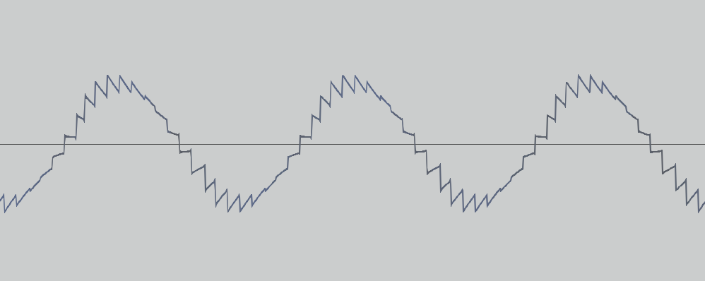
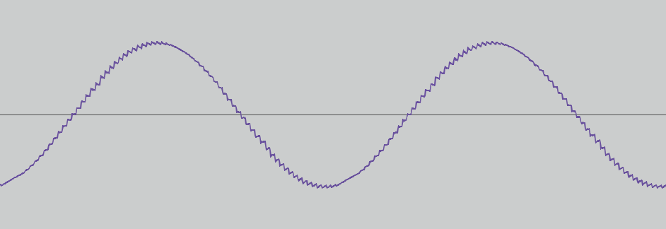
It doesn't seem to work for me... sometimes it makes a reasonable sine wave, but depending on the number of samples and sample rate it usually it makes a vaguely-sine-linke wave with strange artifacts and distortion components, not the correct frequency, etc.

I can ask some more precise questions about that particular code, but I thought I'd check to see if there were any obvious and easy ways to do this that I am overlooking.

Constraints are these:

  • PWM method instead of DAC is probably not an option (AFAIK) as we need frequencies up into 5 or 6kHz
  • super precise frequency is not necessary -- that demo code above actually only approximates the frequency by using timers set to an integer division of the SystemCoreClock.
  • frequency needs to be programmatically selected (i.e. I can't use stored WAV files of sine waves or something like that)
  • ideally we can use the on-board DAC and not an external utility board/shield, though I'm reluctantly open to that if it simplifies things drastically.

I had assumed it would be something like:

SomeAudioLibrary.begin(sample_rate);
SomeAudioLibrary.sineWave(440.0);

...but I'm getting the picture that nothing like this exists? :slight_smile:

Any tips getting me pointed in the right direction are appreciated. I just noticed this post so I'll check that out next to see if there are any appreciable differences to my code.

Thanks!

For questions about code, post the code, using code tags.

Thanks -- see below; I'm mostly curious about the best way to get this job done. I.e. whether I should even bother working with code like this or if there is a more friendly library somewhere to generate sine waves.

From http://forcetronic.blogspot.com/2015/10/arduino-zero-dac-overview-and-waveform.html:

 //This sketch generates a sine wave on the Arduino Zero DAC based on user entered sample count and sample rate
//It was used in a tutorial video on the ForceTronics YouTube Channel. This code can be used and modified freely
//at the users own risk
volatile int sIndex; //Tracks sinewave points in array
int sampleCount = 100; // Number of samples to read in block
int *wavSamples; //array to store sinewave points
uint32_t sampleRate = 1000; //sample rate of the sine wave

void setup() {
  analogWriteResolution(10); //set the Arduino DAC for 10 bits of resolution (max)
  getSinParameters(); //get sinewave parameters from user on serial monitor
  
  /*Allocate the buffer where the samples are stored*/
  wavSamples = (int *) malloc(sampleCount * sizeof(int));
  genSin(sampleCount); //function generates sine wave
}

void loop() {
  sIndex = 0;   //Set to zero to start from beginning of waveform
  tcConfigure(sampleRate); //setup the timer counter based off of the user entered sample rate
  //loop until all the sine wave points have been played
  while (sIndex<sampleCount)
  { 
 //start timer, once timer is done interrupt will occur and DAC value will be updated
    tcStartCounter(); 
  }
  //disable and reset timer counter
  tcDisable();
  tcReset();
}

//This function generates a sine wave and stores it in the wavSamples array
//The input argument is the number of points the sine wave is made up of
void genSin(int sCount) {
 const float pi2 = 6.28; //2 x pi
 float in; 
 
 for(int i=0; i<sCount;i++) { //loop to build sine wave based on sample count
  in = pi2*(1/(float)sCount)*(float)i; //calculate value in radians for sin()
  wavSamples[i] = ((int)(sin(in)*511.5 + 511.5)); //Calculate sine wave value and offset based on DAC resolution 511.5 = 1023/2
 }
}

//This function handles getting and setting the sine wave parameters from 
//the serial monitor. It is important to use the Serial.end() function
//to ensure it doesn't mess up the Timer counter interrupts later
void getSinParameters() {
 Serial.begin(57600);
 Serial.println("Enter number of points in sine wave (range 10 to 1000)");
 sampleCount = readParameter();
 if (sampleCount < 10 || sampleCount > 1000) sampleCount = 100;
 Serial.print("Sample count set to ");
 Serial.println(sampleCount);
 Serial.println("Enter sample rate or samples per second for DAC (range 1 to 100k)");
 sampleRate = readParameter();
 if (sampleRate < 1 || sampleRate > 100000) sampleRate = 10000;
 Serial.print("Sample rate set to ");
 Serial.println(sampleRate);
 Serial.println("Generating sine wave........");
 Serial.end();
}

//waits for serial data and reads it in. This function reads in the parameters
// that are entered into the serial terminal
int readParameter() {
 while(!Serial.available());
 return Serial.parseInt(); //get int that was entered on Serial monitor
}

// Configures the TC to generate output events at the sample frequency.
//Configures the TC in Frequency Generation mode, with an event output once
//each time the audio sample frequency period expires.
 void tcConfigure(int sampleRate)
{
 // Enable GCLK for TCC2 and TC5 (timer counter input clock)
 GCLK->CLKCTRL.reg = (uint16_t) (GCLK_CLKCTRL_CLKEN | GCLK_CLKCTRL_GEN_GCLK0 | GCLK_CLKCTRL_ID(GCM_TC4_TC5)) ;
 while (GCLK->STATUS.bit.SYNCBUSY);

 tcReset(); //reset TC5

 // Set Timer counter Mode to 16 bits
 TC5->COUNT16.CTRLA.reg |= TC_CTRLA_MODE_COUNT16;
 // Set TC5 mode as match frequency
 TC5->COUNT16.CTRLA.reg |= TC_CTRLA_WAVEGEN_MFRQ;
 //set prescaler and enable TC5
 TC5->COUNT16.CTRLA.reg |= TC_CTRLA_PRESCALER_DIV1 | TC_CTRLA_ENABLE;
 //set TC5 timer counter based off of the system clock and the user defined sample rate or waveform
 TC5->COUNT16.CC[0].reg = (uint16_t) (SystemCoreClock / sampleRate - 1);
 while (tcIsSyncing());
 
 // Configure interrupt request
 NVIC_DisableIRQ(TC5_IRQn);
 NVIC_ClearPendingIRQ(TC5_IRQn);
 NVIC_SetPriority(TC5_IRQn, 0);
 NVIC_EnableIRQ(TC5_IRQn);

 // Enable the TC5 interrupt request
 TC5->COUNT16.INTENSET.bit.MC0 = 1;
 while (tcIsSyncing()); //wait until TC5 is done syncing 
} 

//Function that is used to check if TC5 is done syncing
//returns true when it is done syncing
bool tcIsSyncing()
{
  return TC5->COUNT16.STATUS.reg & TC_STATUS_SYNCBUSY;
}

//This function enables TC5 and waits for it to be ready
void tcStartCounter()
{
  TC5->COUNT16.CTRLA.reg |= TC_CTRLA_ENABLE; //set the CTRLA register
  while (tcIsSyncing()); //wait until snyc'd
}

//Reset TC5 
void tcReset()
{
  TC5->COUNT16.CTRLA.reg = TC_CTRLA_SWRST;
  while (tcIsSyncing());
  while (TC5->COUNT16.CTRLA.bit.SWRST);
}

//disable TC5
void tcDisable()
{
  TC5->COUNT16.CTRLA.reg &= ~TC_CTRLA_ENABLE;
  while (tcIsSyncing());
}

void TC5_Handler (void)
{
  analogWrite(A0, wavSamples[sIndex]);
  sIndex++;
  TC5->COUNT16.INTFLAG.bit.MC0 = 1;
} 

Why bother to cut and paste such a mess?

To test the basic idea, you should be able write a simple, self contained example that generates and outputs a sine wave in less than a dozen lines of code.

For example, using PWM on the Uno:

void setup() {
  // generate one cycle of a 60 Hz waveform
  pinMode(3, OUTPUT);
  float sample_rate = 9600.0, freq = 60.0;  //ADC samples/second, AC waveform freq.
  int npts = sample_rate / freq + 1.0;
  for (int i = 0; i < npts; i++) {
    int x = 128.0 + 127.0 * sin(2 * PI * (freq / sample_rate) * i);
    analogWrite(3, x); //PWM output on pin 3
    delayMicroseconds(1.0E6 / sample_rate);  //adjust constant to get correct rate
  }
}
  void loop() {}

Thanks -- My understanding of the demo code I copied above was that it had the advantage of relying on hardware timers for relatively accurate, precise driving of the DAC output... ? But I'd be fine with the more straightforward approach. Did you mean for that for() loop to be in setup()? E.g. just output one cycle of the wave? (I do need a continuous wave.)

I did try to do a simpler self-made version by implementing loop(), using micros() to see where I was in the sine wave and calling analogWrite() once per loop(), but the output was garbled (I'm not actually clear what went wrong, but at any rate, the output was a mess.) Maybe I'll code that up again and seek feedback on it.

Then you must have been using an oscilloscope to see that it was garbled. Please show us what you saw and what part is garbled.

Sort of -- the signal came the audio interface into an audio program -- I'll code it up tomorrow and show you what I mean, thanks.

Hi @savel

Have you tried the observing the DAC output Forcetronics example directly without any additional external circuitry attached?

The SAMD21's DAC has limited drive capabilities, it might be worth placing a voltage-follower op-amp stage at the DAC output.

How the sine wave is implemented depends ultimately on the goal of your project:

If you require a just sine wave with small variations in frequency then the easiest way is to generate the waveform from a wave table and simply adjust the timer's sample rate to change the frequency.

If however you require more variation in the waveform, it might be better to use a fixed audio frequency sample rate (say 32kHz or 44kHz) and employ a wave table in conjuction with linear interpolation to calculate the signal's amplitude plot points along the timebase. This is similar to how wave table synthesizers work, but is much more processor intensive, since the waveform needs to be calculated "on the fly".

I don't have a Zero, but I have generated high-quality sinusoids on the Uno, Nano, etc using a Direct Digital Synthesis (DDS) library with PWM and RC filter output.

I used code downloaded from this site, but it seems to be down now: http://interface.khm.de/index.php/lab/interfaces-advanced/arduino-dds-sinewave-generator/index.html It's a pity, because the code worked very well.

However, I notice that there's an Arduino DDS library for the AVR-based arduinos. Never used it but it looks promising.

Thanks for all the replies! I got a night of sleep and the demo code seems to work well enough now. Not sure what I was doing wrong before. There are numerous distortion artifacts besides the pure sine, but they are like 50+ dB down from the fundamental and that's close enough for me... not sure how much fidelity to expect out of this?

But when I try to adapt it to generate the sine wave on the fly, instead of pre-computing, it does not work. Is this because I am asking too much of the ISR by doing that much math? I know MCU's are not CPU's but I guess I expected it could handle this... ?

The ISR in the demo code is:

void TC5_Handler (void)
{
  analogWrite(A0, wavSamples[sIndex]);
  sIndex++;
  TC5->COUNT16.INTFLAG.bit.MC0 = 1;
}

...which I am changing to:

void TC5_Handler (void)
{
  analogWrite(A0, (int)(sin(curFreq*pi2* ((float) sample_step) / ((float) srate) ) *511.5 + 511.5));
  sample_step++; // (not worrying yet about overflow)
  sIndex++;
  TC5->COUNT16.INTFLAG.bit.MC0 = 1;
}

Even at low sample rates, where I would think there was plenty of time in between interrupts to do the math, this generates a mess... for example, sample rate 1000Hz and a tone frequency of 50Hz generates this (with a fundamental at about 25Hz):

I can precompute the sine wave if necessary... was just hoping the simpler route would work. People use Arduinos to do on-the-fly DSP of audio signals, right, so I figured just making a sine wave would be light weight in comparison?

@cedarlakeinstruments - what is the max frequency with that PWM method? My understanding was that PWM couldn't get up to like 5-6kHz?

@Paul_KD7HB - I coded up my "naive" version again. Code is like this:

int srate;
float curFreq;
float pi2 = 6.283185307179586;

void setup()
{
  Serial.begin(57600); while (!Serial) { ; }
  Serial.println("Enter sample rate.");
  while(!Serial.available());
  srate = Serial.parseInt();
  while (Serial.available()) { Serial.read(); } // flush extra line endings
  Serial.println("Enter frequency.");
  while(!Serial.available());
  curFreq = Serial.parseFloat();
  while (Serial.available()) { Serial.read(); } // flush extra line endings
  Serial.print("Using sample rate: ");
  Serial.print(srate);
  Serial.print(" for frequency ");
  Serial.print(curFreq);
  analogWriteResolution(10); // 10 bit DAC is max on Zero
  analogWrite(A0, 0);
  Serial.flush();
  Serial.end();
}

void loop()
{
  analogWrite(A0, (int)(sin(curFreq*pi2* (((float) micros())/1000.0/1000.0) ) *511.5 + 511.5));
}

...this generates waves that do have a fundamental at the desired frequency, but they are messy with lots of distortion products (though again, better than yesterday for some reason.)

E.g. sample rate 1000 frequency 50Hz:

Sample rate 44100 frequency 440Hz:

simpleway_441ksr_440hz

I presume this is because loop() only gets called every so often (about 4 times per ms, it looks like? ...at least that seems to be the update rate in the resulting wave), the DAC gets updated, and that causes a stairstep (with some ringing) with associated harmonics?

An ISR should be as short and fast as possible: do nothing other than notify the main program that action is to be taken. It should never do I/O, especially anything that depends on interrupts.

I guess the best thing for me to do is to precompute the waves... I'll code it up and see how I get along. Or maybe get an external sig gen shield if necessary.

yes but pre-compile the wave table in the setup function rather than entering it in by hand.

For sure -- the frequency will be adjusted by a rotary encoder so I'll rebuild it every time it changes.

Ok, it's working great, except for two issues;

Issue 1) it's freezing up; I've been playing with the debugger and it looks like when it hangs it's in some kind of deadlock; the timer code (tcIsSyncing()) is doing:

while(TC5->COUNT16.STATUS.reg & TC_STATUS_SYNCBUSY);

...and meanwhile the ISR for the rotary encoder is doing a "delay(1)" for debouncing. The threads seem locked in this state... is there an incompatibility in using delay() in an ISR alongside the hardware timer?

Issue 2) the necessity of rounding the sine wave period to an integer number of samples is probably too coarse a resolution in the upper frequencies (even at 96k sample rate). I think this might drive me to an external sig gen unless there is some clever way around this that I'm not seeing.

I believe he said he had used it at over 44kHz. I was only interested in a 3kHz sine, so that's about where I was testing it.

I'll be darned. I'll have to give that another look.

Meanwhile I recoded to avoid delay() in the ISR and there is no more freezing. But now I'm mired in debouncing/decoding the encoder without delay() and it's proving much harder than I thought. I'll post a separate thread if I need to.

Yes. When you are inside an ISR the interrupts are disabled and so things like delay can not work, because timer 0 can't run.

Debouncing of a rotary encoder should be done by following a state machine so that any bounces are automatically corrected.

Sometimes I have found it necessary to add a 0.1uF capacitor between the encoder pins and ground, just to kill very high frequency oscillations.

Thanks -- if you wouldn't mind me bouncing this encoder question off of you -- I'm getting the impression that the

attachInterrupt(digitalPinToInterrupt(ACHANNEL), handleEncoderChange, CHANGE);

...is kind of "best effort" thing only? I'm asking because the encoder should always end with channel A being high (i.e. when it's in the detente), but I'm often seeing it not sending an interrupt for the high state... I'm guessing that it's in the ISR for the low state when the pin goes high, so it doesn't notice? In other words, an attached CHANGE interrupt can't guarantee an ISR call for every change if they happen during an ISR, right? That makes sense.

I finally got the encoder to work well, though... this is the code I used, in case it's handy to anyone:

#define ACHANNEL 7
#define BCHANNEL 8

unsigned int encoderDebounceMillis = 5;
volatile unsigned long *encoderTimeStamps;
volatile int *encoderBChannelValues;
volatile int encoderHistoryIndex=0;
unsigned int encoderHistoryBufferSize = 200; // worst case number of expected bounces

void setup() {
  encoderTimeStamps = (unsigned long *)malloc(sizeof(unsigned long) * encoderHistoryBufferSize);
  encoderBChannelValues = (int *)malloc(sizeof(int) * encoderHistoryBufferSize);

  pinMode(ACHANNEL, INPUT_PULLUP);
  pinMode(BCHANNEL, INPUT_PULLUP);

  attachInterrupt(digitalPinToInterrupt(ACHANNEL), updateEncoder, RISING);
}

void loop() {
  int encres = checkEncoderHistory();
  if (encres != 0)
  {
    Serial.print("result ");
    Serial.println(encres);
  }
}

void updateEncoder()
{
  encoderTimeStamps[encoderHistoryIndex] = millis();
  encoderBChannelValues[encoderHistoryIndex] = digitalRead(BCHANNEL);
  encoderHistoryIndex = (encoderHistoryIndex + 1) % encoderHistoryBufferSize; // hopefully overflow never happens
}

// return 0 for no movement, 1 for CW, -1 for CCW
int checkEncoderHistory()
{
  int aval, bval;
  if (encoderHistoryIndex == 0) return(0); // nothing in the buffer to check
  if (millis()-encoderTimeStamps[0] < encoderDebounceMillis) return(0);

  aval=digitalRead(ACHANNEL);
  if (aval == 0)
  {
    // stabilized at low, so ignore and reset buffer
    encoderHistoryIndex=0;
    return(0);
  }
  bval=encoderBChannelValues[encoderHistoryIndex-1]; // find the B channel when A last changed
  encoderHistoryIndex=0; // reset the buffer index
  if (bval == 1) return(-1); else return(1);
}

My approach has been to store the ISR events in an array of timestamps with channel B values so I can return from the ISR quickly. Then I poll that array from loop() to check the history and decide when enough debounce time has passed... I can't delay() in the ISR for the bounce to settle, and I can't maintain state and check the pins every loop() because loop() doesn't get called fast enough to catch the necessary in-between state of channel A != channel B, and thus misses as well. I was tracking A channel history, but it's unreliable while it's bouncing and often misses the final high state, so I check it anew in checkEncoderHistory, and just refer to the history array for the B channel's last-seen state while A was shifting.

This MCU stuff is harder than it looks. You guys are impressive. :slight_smile:

Something like that. If you look in the processor's data sheet you will see the minimum time you need for a transition to be detected. If you think about it it can't react faster than the time it takes to execute the ISR. That is where the capacitors come in to just slug the signal a very small amount to allow things to settle.

Also sometimes the encoder doesn't produce that final state due to mechanical reasons. You will pick it up on the next turn.