rcalan:
But, the whole system do not work in the following situation:
What does "do not work" mean in this case?
rcalan:
when the system is solely powered up by li-ion poly battery.
You're putting the battery on the output of the charging IC and powering a 3.3V regulator? That's not how the MCP73831 is designed to be used. The additional load of the regulator will prevent the charge controller from working properly.
As connected, the charge controller probably won't detect the presence of a battery.
I hooked up with some sensors like ADXL362 etc etc with the system. "do not work" means it do not output any signal into my serial monitor.
The problem is like,
The system work when i connect with an external 3.3v powered by another arduino board.
but it didn't work when i connect with an external li-ion poly battery.
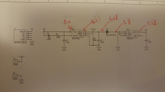
I have just measured the voltage at every point (after the MCP73831, before and after the diode, after the regulator) and all are normal in all cases.
It is connected to the VBatt and GND.
Yes. It is charged with 4.1V and i have try using another batt (210mah) which is also 4.1v, but failed.
It charges up the Battery. But at this point, the situation is quite weird that it works well when 3.3v power supply from other arduino board and attached to the VBatt and GND. However, it doesn't work
when the system is solely powered up by li-ion poly battery by attaching to VBatt and GND.
P.S. Doesn't work means the voltage at different point are correct, but the sensors do not give any signal to the serial monitor.
Hopefully the situation is more clear now. Many thnaks!
rcalan:
I have just measured the voltage at every point (after the MCP73831, before and after the diode, after the regulator) and all are normal in all cases.
What are the voltages? "Normal" doesn't mean anything. And what is connected at the time you are making the measurements.
rcalan:
the situation is quite weird that it works well when 3.3v power supply from other arduino board and attached to the VBatt and GND.
This suggests your circuit is not wired as the schematic shows. Or it suggests you didn't actually measure the 3 points with a multimeter.
There is no way you will get 3.3V out of the regulator when you put 3.3V in at Vbatt. You'll lose 0.5V through the shotcky diode and you're going to see about a 0.4-0.7v drop through the regulator. At best, you will have 2.3V on your 3.3v line.
If your meter shows 3.3V on the regulator output when you put a 3.3V source on Vbatt, then something is not wired correctly.
Hi,
Can you mark on your circuit diagram the voltages that you have measured.
With the battery being charged.
With the battery being charged and the 3.3V output connected to your load.
What is you 3.3V output load?
How much current is running through your load?
With charging turned off and 3.3V output connected to your load.
Thanks.. Tom...
PS. Please itemize your answers like my questions.
TomGeorge:
Hi,
Can you mark on your circuit diagram the voltages that you have measured.
With the battery being charged.
With USB (5V) and battery (VBatt) attached. Please refer to Attachment A.
TomGeorge:
2) With the battery being charged and the 3.3V output connected to your load.
What is you 3.3V output load?
How much current is running through your load?
Sorry that i havent check, let me get check it later today.
TomGeorge:
3) With charging turned off and 3.3V output connected to your load.
With no USB plugged in, attachment C
Furthermore, I have tried to attach 5V right after the diode and the voltage at different point are in attachment B.
I have just tested the voltage of different point.
Attachment A- with USB (5V) and li-ion batt (VBatt) attached
Attachment B- with 5V (from other arduino board) supplied to the system right after the diode
Attachment C- with a li-ion batt at (VBatt)
The LDO with no load will regulate down to 10mV differential.
General Description The MIC5219 is an efficient linear voltage regulator with high peak output current capability, very-low-dropout voltage, and better than 1% output voltage accuracy. Dropout is typically 10mV at light loads and less than 500mV at full load.
Is the battery connected in Att A?
That is the arrangement in Att C, you have 3.27Vdc output, whats the problem?
What are you expecting?
If Att C is not the solely power by li-ion, then show us the voltages when you are trying to power the system with solely the li-ion.
Tom....
PS. Can you post a pcture of your project, with battery connected, so we can see your component layout?
I have attached (refer to attachment A) my full schematic of my project, its about using simblee module to read data from ADXL362. The schematic is actually reference the simblee lilypad from sparkfun. LilyPad Simblee BLE Board - RFD77101 - DEV-13633 - SparkFun Electronics. the only different is just i am using the original rfduino usb shield, but sparkfun uses the 5V FDTI.
I have also tried to hook up my previous simblee board with different scenarios to see if there are actually some problem to power up by other sources, and i found out there are some problems. I have attached a full picture (Attachment B). Not working means i cannot upload any program nor read the data from the sensor. It shows UART TIMEOUT FAIL...FAIL...FAIL...