Battery capacity measurement using a Keyestudio power module

Hello,

So for some background info, I'm currently working on repurposing the Keyestudio dual axis solar tracker kit for a project and the last hurdle I need to get past is implementing a way to measure and then display the remaining battery capacity.
This kit comes with a lithium power module that uses that battery to power the board using the V and G pins, which I connected to VIn and GND respectively as shown in this photo:

So the problem is that I need help with measuring the battery output voltage via the Keyestudio power module in order to measure the capacity of the battery, on the official site it states that "the pin S can read the battery voltage after the resistance 1/2 voltage." which, if I understand correctly, should in theory help me achieve my goal assuming it outputs the battery voltage value BEFORE it gets raised by the module.

The site isn't very descriptive of it, the module has no identifying code written on it or anything I can go off of to find it or at least a module that works in a similar way so I can go off of that. Here is a closer picture of it in case it helps.

So my question is, would I be able to use the S pin to ideally get the battery output voltage and use it to measure the capacity? Or would I need a separate module to be able to do that? I know that I'll also have to do the code, that is a different beast but I should be able to figure it out on my own from there on.

Here is the datasheet of the Uno board for some context on the wiring.

The pins on the board that are taken up so far are the A0 through A3(number 25 male pins) by the photoresistors, the number 26 pins are also taken up by the BH1750, and the digital pins are taken up by the two servos, dht11, button and buzzer, but those are likely irrelevant for this, and A4 and A5 are taken up by the LCD I2C as shown here:

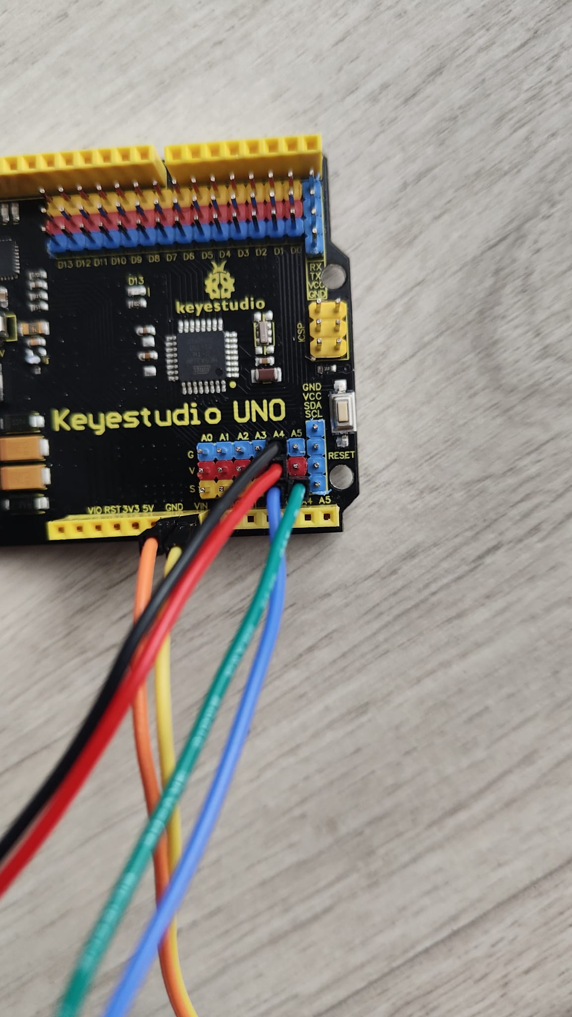
Those I am planning to move to the 5V and GND pins (number 23 and 4, respectively) and SDA and SCL pins (number 7 and 8, respectively), in order to make room for one of the analog pins to be used to measure the voltage level which I will connect to the number 25 A4 or A5 female pins, since I assume I won't be able to use them while the LCD is connected to them at the same time.

That should hopefully explain what I am after, if you need any more info I will be happy to provide it!

The output at the S pin will be the battery voltage divided by 2
So if the battery goes from 4.2V to 3.0V, the voltage at S will go from 2.1V to 1.5V
You can connect the S pin directly to any of the analog pins on the UNO
Make sure you also connec the G pin the the Uno GND

1 Like

Ok, I redid the wiring and everything seems to be in order hardware wise, but the voltage value is off, all I'm doing is using the basic voltage reading code, I have a Samsung 25R battery connected and at full charge it returns 3.17.

void setup() {
  // initialize serial communication at 9600 bits per second:
  Serial.begin(9600);
}

// the loop routine runs over and over again forever:
void loop() {
  // read the input on analog pin 5:
  int sensorValue = analogRead(A5);
  // Convert the analog reading (which goes from 0 - 1023) to a voltage (0 - 5V):
  float voltage = sensorValue * (5.0 / 1023.0);
  // print out the value you read:
  Serial.println(voltage);
}

Battery voltage is always determined by the chemistry used in the battery. The capacity is the CURRENT the battery can supply for a certain time period. You can have a dead battery that will show the correct voltage, but can supply ZERO current. While measuring the dead battery voltage, the tiny current necessary to make the voltage measurement will cause the measured voltage to begin dropping.

My mistake, by capacity I mean state of charge, specifically as in the remaining percentage of the battery, that can use voltage in order to be measured, hence why I asked about it.

I tried to tell you the voltage does not show the state of charge unless you are drawing a significant current while making the voltage measurement.

Does using the battery to power the Arduino, the LCD, the servos, the sensors and the smartphone charger module not count as a significant power draw?

Yes, probably enough current to reduce the floating voltage value. You will need to keep track of the voltage at that current to monitor the capacity reduction with age.

Something wrong there, you should not see anything over 2.1V
Are you sure you are connected to the S pin and NOT the V pin?

Yes, I am positive, S pin is on A5, V pin is on Vin and G is on GND.

I'm reading the base analog value and it keeps hovering in the 968-975 range.

The V pin should not be connected to anything

Well that's going to be a problem, but even with the V pin disconnected it still shows the same values, so something is telling me that this S pin is not doing what it's supposed to do.

I'm going by the schematic they show on the webpage. The battery is directly connected to a voltage divider that cuts the voltage in half.

However first you said your were seeing 3.17V, then you said the ADC readings were around 970 and that would be 5*970/1024=4.74V.
So I not sure what is wrong.

On your Uno connect the 3.3V pin to A5 and see if you read 3.3V

Don't use A5 if you have the LCD connected, use A0

You haven't taken the voltage divider in to account.
The battery voltage is twice as much as you are measuring.

Yes, so connecting it to A0 does give me 2.22-2.24, which is closer to what it should be, but the problem again is that pins A0, A1, A2 and A3 are taken up by the photoresistors, I figured that if I were to move the LCD from A4 and A5 to the SDA and SCL pins at the top of the board they wouldn't interfere, since I have a BH1750 connected which also uses SDA and SCL pins and it doesn't interfere with the LCD either.

If it designed like a Arduino Uno then the SDA SCL pins are directly connected to the A4, A5 pins
You might be out of luck.

So have you got any of your I2C devices connected at the moment?

You can't use A5 as both an analogue input and I2C at the same time. You have to choose one or the other.

Yes, I have both the LCD and the BH1750 connected at once, so I'll have to compromise on the battery capacity then, that's alright, thanks everyone!

You could use a multiplexer (MUX) to switch the A0 pin between reading the battery and the photosensor