Hello all. I've just taken my very first stab at PCB design, and I thought it would be cool to build a sort of "extension board" that the ESP01(s) can clip into. The idea is it's USB rechargable, has a LiPo battery (250mAh, max charge/discharge 2C), a button connected to GP0, and an on/off switch. Here's my version 1 schematics, is there anything I'm doing wrong, or something I could do better? I'm trying to learn, thanks in advance!

Nice schematic but hard to read. Normally signals, power, etc go from top down and left to right. So your Vcc would be on the upper part and the ground on the lower part. I would highly recommend you add some high frequency bypass capacitors maybe in the 100nF range.
The AMS1117-3.3 has a high dropout voltage.
Wrong choice for a single LiPo cell.
It needs at least 4.5volt to produce a stable 3.3volt@100mA.
Leo..
Thanks for the help, that saved me tons of time debugging. I'll find a better replacement. Would something like the "AZ1117C-3.3" work? It says it has a very low dropout voltage (looks like ~1.7v) and outputs 3.3v.
In the meantime, does everything else look okay? The general structure of the circuit? I haven't done much work with LiPo batteries, so I want to make sure everything is looking good before I design the PCB and get the order in.
Same regulator made by another factory. Look at the dropout voltage (at 100mA) in the datasheet. You need a regulator that drops no more than 0.1volt at that current.
Leo..
My mistake, I had an incorrect understanding of a dropout voltage rating. I'll try to find an alternative
Have a look at the Seeed ESP32-C3.
It has a more modern ESP32 and built-in LiPo charger.
Leo..
I've made a newer version of the schematic, with an updated LDO voltage regulator, which should play nicely with a LiPo battery.
Study the AP2210 datasheet.
Voltage regulators need specific capacitors (types and values) on their inputs and outputs.
They will oscillate when you get that wrong.
Leo..
Well the LiPo side of things is actually not how i would do it. The main issue is that the TP4056 does not allow for load sharing. That means that if the unit is on while charging the battery, the battery may end up being overcharged which can cause it to get damage and possibly explode. Of course if you never have the unit switched on while charging there is no problem. The other thing is that the circuit does not have a low-battery shut-off circuit, which may result in the battery being depleted beyond it's range, causing it to break. Nor is there any over-current protection. Some batteries do have circuitry for that on board, but it would be better to have it as part of the circuit.
That's very helpful info; I was figuring that the TP4056 would handle the first issue (I guess not), and also that the voltage regulator would eventually stop flow from the battery when it got too low. How would you integrate these things?
Here is a new and improved version. I've gone through the datasheets for these ICs and put in the caps and resistors that they call for.

As for the low voltage protection i use a FS312G icww a FS8205 dual mosfet.

No unfortunately not. The current flowing in the rest of the circuit will confuse the TP4056 into not coming to the end of it's charging cycle.
The simplest solution is using 2 diodes, but the voltage drop when aiming for 3.3v thru a regulator is probably not going to ok, and anyway wasteful i guess. But there are solutions with 2 mosfets switching either channel (batery or 5v in) when 5v is present on the input.
Perhaps, gasp!, an SPDT switch - so that the battery is either connected to the TP4056 or running the ESP.
That really might be the way to go. I might change the two-state switch on the board to switch between connecting BAT+ to the TP4056 and BAT+ to the voltage regulator, if that would work.
You could use an adjustable "boost module" (find one with a small-ish footprint, 1-in sqr.)
Trace layouts and so on, with regard to step-up/down ICs can be, usually are, critical.
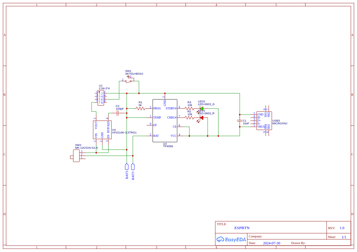
Going off of the switch idea, this is what I've come up with (I've also reformatted the schematic to make it a bit easier to read):

Did you read NOTE 4 of the data sheet?
- Dropout voltage is 250mV when TA = +25oC. In order to obtain a normal output voltage, VOUT+0.25V is the minimum input voltage which will result a low
PSRR, imposing a bad influence on system. Therefore, the recommended input voltage is VOUT+1V to 13.2V. For AP2210-3.0 version, its input voltage
can be set from 4V (VOUT+1V) to 13.2V.
That would be 3.3+1 = 4.3V
Lipo projects for 3.3v device tend to suffer from this issue a lot. Any recommendations for a regulator. I tend not to use ERSP with LiPo, partly for their power hungry nature.
Found a new chip, seems promising (I think I used it originally, but scrapped it for some reason or another): XC6222. It has a very low dropout voltage (~100-200mV in the conditions I'll be using it in). That should work, since the battery will run somewhere between 3.7 and 4.0 volts. I'll do a bit more research on this IC for things like capacitors it needs to prevent oscillating, resistor values, etc., but is there anything else wrong with my circuit? In theory, the battery should have an internal protection chip to prevent over/under-charging, so is everything good to ship? Am I missing anything obvious?
Either it does or it doesn't. You are usually able to see a part of the circuit.