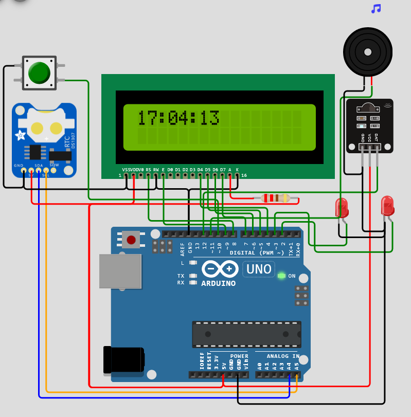
Im trying to make an alarm clock using an Arduino Mega 2560 R3, a DS3231 clock module, a 1602 LCD display, two LEDs, a button, a buzzer, a controller and a TL1838 Universal IR Infrared Receiver, each of the components will be connected on a breadboard.
The button and the potentiometer are not necessary. I was just proving something.
This is the code:
#include <Wire.h>
#include <RTClib.h>
#include <LiquidCrystal.h>
#include <IRremote.h>

RTC_DS3231 rtc;
LiquidCrystal lcd(8, 9, 4, 5, 6, 7);
IRrecv irrecv(12);
decode_results results;
int led1 = 2;
int led2 = 3;
int button = 10;
int buzzer = 11;
int alarmHour = 0;
int alarmMinute = 0;

void setup() {
  lcd.begin(16, 2);
  irrecv.enableIRIn();
  pinMode(led1, OUTPUT);
  pinMode(led2, OUTPUT);
  pinMode(button, INPUT_PULLUP);
  pinMode(buzzer, OUTPUT);
  rtc.begin();
  rtc.adjust(DateTime(F(__DATE__), F(__TIME__)));
}

void loop() {
  DateTime now = rtc.now();
  lcd.setCursor(0, 0);
  lcd.print(now.hour(), DEC);
  lcd.print(":");
  lcd.print(now.minute(), DEC);
  lcd.print(":");
  lcd.print(now.second(), DEC);

  if (irrecv.decode(&results)) {
    switch (results.value) {
      case 0xFFA25D: // "1" button on remote
        alarmHour = (alarmHour + 1) % 24;
        break;
      case 0xFF629D: // "2" button on remote
        alarmMinute = (alarmMinute + 1) % 60;
        break;
      case 0xFFE21D: // "3" button on remote
        digitalWrite(led1, LOW);
        digitalWrite(led2, LOW);
        break;
    }
    irrecv.resume();
  }

  if (digitalRead(button) == LOW) {
    if (now.hour() == alarmHour && now.minute() == alarmMinute) {
      digitalWrite(led1, HIGH);
      digitalWrite(led2, HIGH);
      tone(buzzer, 1000, 1000);
    }
  }
}
And this is the pictures of the arduino and the components:
So, the problem is that i cannot see any errors on the code or the connections of the wires.
And still it doesnt work. It suppose to give me the real time, and the time in the lcd.
As i say to the other person:
So, the problem is that i cannot see any errors on the code or the connections of the wires.
And still it doesnt work. It suppose to give me the real time, and the time in the lcd.
Do you see any errors?
Keep it simple and stupid firstly.
Follow up separatly the example code that comes with the library or
run some tutorials for the hardware selected.
If you are happy with the results of the tutorials you can merge these to your project.
Did you write all that code at once. OR
Did you develop it in stages, and get each stage working before going onto the next.
Then when all stages are working , add them together ONE at a time, each time getting the new code to work.
Have you got code that JUST tests the display?
Have you got code that JUST operates the buzzer and LEDs?
Have you got code that JUST reads the IR receiver?
In other words have you proven ALL your hardware separately before combining each stage, one at a time into your final code?
you posted two pictures but it is impossible to really check if the wires are connected the correct way.
The components all can interfere on hardware-sode and software-side to make it not work
so you have a lot of things that can (but must not) interfere in the wrong way.
I don't recommend it You could do wild guessings
maybe if I .....
maybe if I .....
maybe if I .....
....
_1001. maybe if I .....
without finding the bug even after weeks.
I recommend systematic testing each part on its own.
This is the reason why you should roll back to a much simpler code that does just test one single component.
For each of your components there are demo-codes that are well proven to work (on the software-side) So these dmo-codes can be used to check if there is a hardware-problem
And you should use serial printing to make visible on the serial monitor what your code is doing.
Except for high-performance applications printing to the serial monitor at 115200 baud does not interfere with the rest of your code
So with which part would you like to start testing?