[Beginner] help me wrap my head around controlling a single 12V RGB LED

Please be gentle... I'm very much a beginner who embarrassingly still struggles to wrap his head around transistors. I just need more practice actually using them so I understand things better.

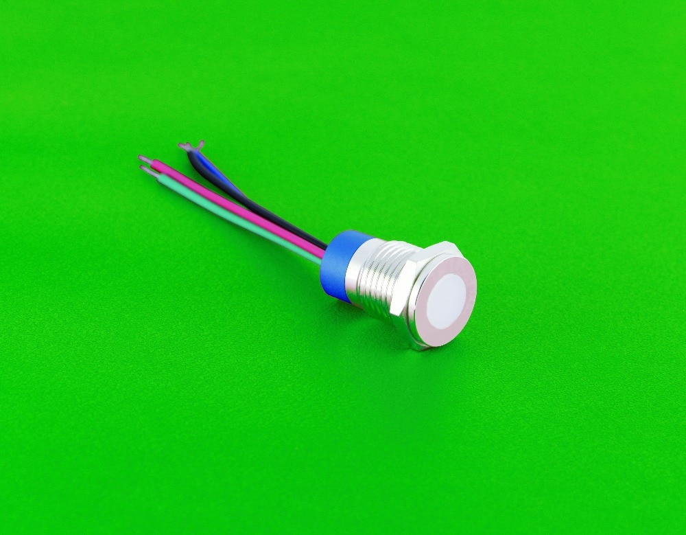
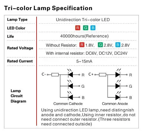
I have a single 12V RGB LED that I'd like to control from 3 PWM pins. The one I have on hand happens to be common cathode, which I understand is unusual, however I had ordered a CC one because the tiny RGB that came with my starter/learner kit was CC and I didn't understand why one might be better than the other. Now, since it's 12V I know I can't drive it directly from the Arduino (mine is a Teensy 3.2 which uses 3.3V) and will need to use transistors. I have a variety of PNP and NPN transistors on hand, such as the BC337 (NPN). Since it's just a single RGB LED, I read that each segment should only use about 20mA so pretty much any of my transistors should be able to handle the current (the BC337 is rated for 800mA). I also have a variety of resistors on hand.

I'm struggling with understanding whether I should be using PNP or NPN transistors for this. I think with that sorted out, I can probably figure out the wiring. I did find this which is close to what I'm trying to accomplish:

However that appears to be for common anode, not common cathode. So I don't know if I rework the wiring for CC whether I can still use NPN transistors as shown, or are PNP transistors then needed? Then I see some diagrams where two transistors are used per channel and then I'm really confused.

Currently I'm just prototyping on a breadboard using what I have on hand, but I imagine I might opt for something like a ULN2003 for the final project.

Acceptable answers can include "wait until you get a ULN2003, it'll make your life easier" and/or "ditch the CC RGB and order a CA RGB instead" as I'm not in any rush.

Thanks in advance. :slight_smile:

sremick:
Currently I'm just prototyping on a breadboard using what I have on hand, but I imagine I might opt for something like a ULN2003 for the final project.

Bleeah!

Please don't go buying junkyard (obsolete) parts, even if that is what they cleverly dump in some Arduino "starter kits"! :astonished:

OK, now 14 posts to date, I would have thought you had at least read the instructions and comprehended the need to cite exactly what part you have on hand when you ask for help. When and if you do that, we might better understand what is involved and the easiest way to operate it. :grinning:

Paul__B:
Bleeah!

Please don't go buying junkyard (obsolete) parts, even if that is what they cleverly dump in some Arduino "starter kits"! :astonished:

Sorry... it wasn't a part I already had, but was something my research had lead me to learn was an AIO potential solution targeted for just the sort of thing I'm doing. Unfortunately the newcomer who finds dozens of mentions on the internet of a possible solution doesn't always also find the one that says "X part is now outdated, use Y instead." Happy to learn what the better/newer option would be.

OK, now 14 posts to date, I would have thought you had at least read the instructions and comprehended the need to cite exactly what part you have on hand when you ask for help. When and if you do that, we might better understand what is involved and the easiest way to operate it. :grinning:

Well, I have a lot, and am not locked-in to what I have and am happy to acquire additional parts. Transistors I have already include: BC337, BC327, 2N2222, 2N2907, 2N3904, 2N3906, S8050, S8550, A1015, and C1815. I also have IRFZ44N MOSFETs but I imagine those would be overkill. For resistors I have (ohms) 10, 100, 220, 330, 1K, 2K, 5K, 10K, 100K, 1M and am ordering some 4.7K ones already.

Since I'm happy to go obtain whatever alternate/better components I need, I was just trying to keep the post concise. If I was told the solution involved parts I didn't happen to already have, I'd just go get them.

I have 12V, 5V and 3.3V power available already, and am running a Teensy 3.2 for this project which uses 3.3V itself so that's what its data lines are going to be.

I don't have any specs for the RGB LED other than that it is (supposed to be) common-cathode.

sremick:
I don't have any specs for the RGB LED other than that it is (supposed to be) common-cathode.

Well, I don't think that is going to get us anywhere.

Is it actually in your possession? Form where did you obtain it, and how? Is there a Web site for it? If no answers at all to these, or insufficient answers, let's also have pictures, taken in outside daylight, perfectly focused and no less than 4 Megapixels. :sunglasses:

Paul__B:
Well, I don't think that is going to get us anywhere.

Is it actually in your possession? Form where did you obtain it, and how? Is there a Web site for it?

Yes, I have it. Here it is:
https://www.aliexpress.com/item/33062963590.html

I inquired whether it was CA or CC... he said CC upon request, so I requested CC and I have it in my possession.

Well, it is going to be a problem for sure given that you clearly ordered the wrong part (version)! :astonished:


According to the circuit diagram, it is unsuitable for colours other than the three primaries as it has a common resistor.

This means that if you connect more than one colour at a time, only one will light (properly).

Have you actually tried it on a 12 V supply? Or more practically, on a 5 V supply, since (now we know what it is, we can say) it will operate on a 5 V supply?

Given that it is specified for 15 mA - and that presumably if you connect it to 12 V - you can try simply connecting it directly to the Arduino pins and experiment. :grinning:

Heh... well, you're right. I just tried it. Red, green, or blue... pick one, that's it. Ah well, live and learn. Back to searching and shopping.

So now I know: make sure there's no internal resistor. And I assume I should be looking for common-anode?

I had opted for 12V because 1) I wanted it to be as bright as possible, and 2) I knew I'd have 12V available since that's my native voltage that I'm converting down from. But I also now have 5V available.

sremick:
So now I know: make sure there's no internal resistor. And I assume I should be looking for common-anode?

If operating from 5 V, it doesn't matter, since you need no additional components (apart from resistors, if you obtain the version with none), at 15 mA (or less now), the Arduino will drive it directly. :sunglasses:

sremick:
I had opted for 12V because 1) I wanted it to be as bright as possible,

Which is dead wrong! :astonished: All versions contain the same LEDs, and it is the current that they carry which determines the brightness. The resistors in each version are selected to provide that same current by wasting (as heat) the difference between the supply voltage and the 2.8 V of the LED. More voltage, more waste! :roll_eyes:

sremick:
and 2) I knew I'd have 12V available since that's my native voltage that I'm converting down from. But I also now have 5V available.

And that was also wrong, since you must have a 5 V supply to operate the Arduino whatever other voltage you happen to have. :roll_eyes:

Paul__B:
All versions contain the same LEDs, and it is the current that they carry which determines the brightness. The resistors in each version are selected to provide that same current by wasting (as heat) the difference between the supply voltage and the 2.8 V of the LED. More voltage, more waste! :roll_eyes:

Ah, good to know.

And that was also wrong, since you must have a 5 V supply to operate the Arduino whatever other voltage you happen to have. :roll_eyes:

Actually, as I mentioned in the OP I am using a Teensy 3.2. This version operates on 3.3V and the logic pins drive at 3.3V as well. So I convert from 12V -> 3.3V for both the Arduino as well as the controller for the e-paper display which was also specifically selected to operate on 3.3V power as well as 3.3V logic. The only reason I have 5V available as well was that earlier I was experimenting with an LCD display that required 5V power, so I left the voltage converter in in case something else came around that needed 5V (common).

Well, it gets a bit close and I am not sure of the Teensy's current drive capability, so you would need to carefully calibrate the resistor values for the LEDs (specified at 2.8 V).

There is one trick.

If you have a 3.3 V processor, you can use common anode LEDs connected to the same 5 V supply from which the 3.3 V is derived. As the LEDs will not conduct at less than 1.7 V (well, the red may slightly, you can just add a series diode if that is a concern), they will not tend to pull the processor's output pins above the 3.3 V supply which would be undesirable.

Nothing wrong with common cathode.
A part like MIC2891 will buffer 5V signals and drive 12V to the anodes if that is what is needed, with the CC of the LED connected to Gnd.
https://www.digikey.com/en/products/detail/microchip-technology/MIC2981-82YN/771627

OK looks like I can order them w/o internal resistors, and my choice of CC or CA:

I assume ordering a CA version w/o resistors would solve many of my problems?

It would certainly be easier to use. :grinning:

Paul__B:
It would certainly be easier to use. :grinning:

Ok I'll get it ordered. While I'm ordering things:

  1. Are there specific transistors you'd recommend, or would the ones I already have work?
  2. The RGB LED w/o resistors wants 1.8V and 2.8V. What would be the ideal resistor values to be using? Your post made me concerned about not doing this in the "best" way"
  3. Instead of the ULN2003, is there some other chip I should look into obtaining to make my life easier? MIC2891? Something else?

Or, here's another idea:

Get something like the Apex Q8F8BZZRYG02E. This is a common-cathode, but it operates at 2/2.1/2.2V and only draws 20mA per segment. The Teensy can handle 25mA per data pin.

Then I don't need transitors, and I just get some resistors sized to drop the 3.3V to the 2.xV needed for each pin. Just wire direct from the data pins to resistors then to the pins on the LED, and then ground the LED to common ground.

The LED isn't full RGB but I can live without that... as long as I can produce green, red, and yellow/amber from the same LED I'm happy.

Yes, the Apem Q8F8BZZRYG02E requires lower voltages because it does not have a blue LED.

Have you tried the blue LED that you already have connected to a pin on your Teensy? That is of course, perfectly safe as it will draw very little current.

As to the resistor values that you would use in the final version, given that they limit to less than the maximum safely specified for the Teensy, the answer is to try different values above that minimum as you may want to balance out the brightness of the different LEDs.

sremick:
The Teensy can handle 25mA per data pin.

Sure about that? Can you post a link to a reliable source, like the PJRC site, that says that? I can imagine that might be the absolute max. Other 3.3V MCU have quite low limits, eg. 12mA.

EDIT: yes it is 25mA source or sink per pin according to page 10 of the data sheet.

Well now I'm seeing things that suggest the actual current max is 10mA/pin. So looks like we're back to needing transistors. :frowning:

I already have the Q8F8BZZRYG02E (common cathode) on order. So if that's not going to work and I need to get something else that's common-anode, let me know.

Unfortunately despite all the broad-level discussion in this thread so far, still don't understand what I need and how it wires up. :frowning:

  1. If use a CC LED like the Q8F8BZZRYG02, do I need NPN or PNP transistors?
  2. Do I then then use 60-ohm & 75-ohm resistors to get the appropriate voltage from the 3.3V line to the LED? Or 160/145 ohm if using the 5V source?
  3. Should I avoid CC like the plague and get a CA LED? In which case I believe I use NPN per examples I've seen?
    Well

I ended up just using a photoMOS relay. Ended up being a lot simpler and straight-forward.

It's working great.

This topic was automatically closed 120 days after the last reply. New replies are no longer allowed.