beginner - problems

Since a few days ago by the user Arduino Uno and I made a couple of projects and almost everything I could from vido clips from joutube.

Now I tried to make something complicated project, at least for me.

I managed to get through 4 button and a few resistors make the analog input to -A0 who commands the relays at the outputs 13,12,11,10.

This match trying to find a way to change this code with several conditions.

The first condition:

If the pin 2 (LOW) read analog input from A0
if pin 2 (HIGH) read analog input from A1

The second condition:

If I'm reading the analog input A1
Powered some type of automatic mode and pin 13 (HIGH) for 20s or until you activate microswitches 1 or 2,
then activates pin 11 for a period of 5 seconds or until you activate microswitches 3 or 4
and so on until you activate microswitches 4 and 2 then activates pin 10 until you activate microswitches 3 and then pin 12 until you activate microswitches 2

microswitches 1 - the beginning of the path X-axis
microswitches 2 - end path X- axis
microswitches 3 - the beginning of the path Y-axis
microswitches 4 - end path Y- axis

Pin 13 - Engine 1 go left
Pin 12 - Engine 1 go right
Pin 11 - Engine 2 go left
Pin 10 - Engine 2 go right

I need help for changing the code

sorry for bad English

Relay.txt (3.36 KB)

just a quick question, am I reading this right? Do you use a switch on the analog input?
If so, Why?

Wouldn't tt be easier to do it on a digital port?

The diagram shows the 4 button and switch that changes the analog pin A0 to A1.
when I worked Electronics will be two groups for each analog input A0 with 4 button on the A1 I put 4 microswitch.
Perhaps mode and instead of A1 to go via the digital inputs with microswitch.

But I can not write code that we include A0, when needed, and the second part is more important that we give conditions for the automatic mode when I choose.

The unit planning to implement in a lathe for wood blade control for processing.

Manual that I donated doing what needs perfectly.

I need a second piece of code that will work automatically prko template until you activate the microswitch for the final position of the Y-axis.
Then must return to the starting position.

The initial position is activated microswitches 2 and microswitches 3

And condition for this is that the activated microswitches 2 and microswitches 4

I have looked at your code and at you nice clear diagram but I cannot make sense of your problem.

It is not helped by the diagram not having anything connected to pin 2.
And, as @Kevin77 says, why use analog inputs to detect switches when digital inputs would be simpler?

Maybe you could write down what you want to happen step by step in this style

Pin2 LOW
XXX happens

Pin2 HIGH
Switches 1,2,3,4 LOW
nnnn happens
Switch1 HIGH
aaa happens
Switch2 HIGH
bbb happens

...R

I will try to explain the concept

Pin 2 - LOW
	analogRead A0 and do not read pin A1
Pin 2 - HIGH
	analogRead A1 and do not read pin A0

this works - OK
	analogRead A0
push S1
	digitalWrite Pin13
push S2
	digitalWrite Pin12
push S3
	digitalWrite Pin11
push S4
	digitalWrite Pin10

S1,S2,S3 and S4 is http://cdn2.erusa.com/wp-content/uploads/2013/07/sw130_large1.jpg?0c0378


This we now need - 


Pin 2 - HIGH
	analogRead A1 and do not read pin A0
	digitalWrite - pin 10 - HIGH
until	
	S8 - HIGH
Then
	digitalWrite - pin12 - HIGH
until
	S5 - HIGH

This is the starting position

Now

pin 3 - LOW 
	not doing anything
pin 3 - HIGH
	doing this
	digitalWrite - pin13 - HIGH
until
	S5 - HIGH then
	digitalWrite - pin11 - HIGH
	daley(2000)
Then
	digitalWrite - pin12 - HIGH
until
	S6 - HIGH then
	digitalWrite - pin11 - HIGH
	daley(2000)
Then 
	digitalWrite - pin13 - HIGH
until
	S5 - HIGH then
	digitalWrite - pin11 - HIGH
	daley(2000)
Then
	digitalWrite - pin12 - HIGH
until
	S6 - HIGH then
	digitalWrite - pin11 - HIGH
	daley(2000)

is repeated until
	S7 - HIGH
Then
	digitalWrite - pin 10 - HIGH
until	
	S8 - HIGH
Then
	digitalWrite - pin12 - HIGH
until
	S5 - HIGH

END


Pin13 - HIGH - motor1 run left 	X-axis
pin12 - HIGH - motor1 run right X-axis
Pin11 - HIGH - motor2 run UP	Y-axis
pin10 - HIGH - motor2 run Down	Y-axis

S5 - read switch - X-axis left
S6 - read switch - X-axis right
S7 - read switch - Y-axis UP
S8 - read switch - Y-axis Down

S5,S6,S7 and S8 is 
http://www.chaldon.co.uk/wp-content/uploads/2009/07/4561.jpg

S1,S2,S3 and S4 is
BUTTON

S5,S6,S7 and S8 is
read switch

What program did you use to represent your circuit?

Arduino-beginner:
I will try to explain the concept

I have looked at this reasonably carefully but I won't pretend to understand it.

However it looks sufficiently close to workable code that it would be worth while trying to build it into a program.

I don't know what your native language is, and I apologize that I only know English, but unfortunately, there is a major language barrier which is making it very difficult to help.

I had hoped that your response to my Reply #3 would have been an attempt to describe your project in the style - if the user presses S1 motor B should run FWD for 10 seconds (or whatever). A description that does NOT use Arduino code would be best.

...R

I am from Serbia

Pin2 - LOW
read pinA0

Pin2 - HIGH
read pinA1

this works pinA0
S1 - push
pin13 - HIGH
S2 - push
pin12 - HIGH
S3 - push
pin12 - HIGH
S5 - push
pin10 - HIGH

this works pinA1
pin2 - HIGH
read pinA1
pin10 - HIGH until S8 - HIGH
pin12 - HIGH until S5 - HIGH

Pin3 - HIGH
pin13 - HIGH until S5 - HIGH
pin11 - HIGH (2s)
pin12 - HIGH until S6 - HIGH
pin11 - HIGH (2s)
pin13 - HIGH until S5 - HIGH
PIN11 - HIGH (2s)
pin12 - HIGH until S6 - HIGH
pin11 - HIGH (2s)
S7 - HIGH
pin10 - HIGH until S8 - HIGH
pin12 - HIGH until S5 - HIGH

end

I'm trying to do something like this
Semi automatic wood lathe

pure_struggle:
What program did you use to represent your circuit?

I use Proteus 8 with arduino uno addition

Arduino-beginner:
I am from Serbia

Hello to Serbia, and welcome.

As I said earlier I think the best next step is for you to develop your list of steps into a program. I'm not sure whether you know how to do that?

You may find some useful ideas in planning and implementing a program

...R

Thanks for your help

Only a few days ago I started to learn Arduino.

And I immediately imagined useful from this device.
But I see that it is not easy.

Arduino-beginner:
Only a few days ago I started to learn Arduino.

There are many useful example programs included with the Arduino IDE. Study some of them. Make copies of them and try modifying them so that you can learn how the system works.

Then write a short program that, perhaps, reads your Pin2 and uses it to choose between reading A0 or A1 and displays the value from A0 or A1 on the Serial Monitor.

It is very important to develop your project in small steps making sure you understand each part before you move on to the next. If you try to do it as one big mouthful you will choke.

...R

what you are trying to produce is a type of a "finite state machine"

basically, the machine starts in state "0" (zero), which is, all motors off

if you press button "A" then the machine exits state "0" and enters state "5" (just an example)

state "5" ... starts 20 second timer and jumps to state "7"

state "7" ... motor #1 runs in clockwise direction ... also watches travel limit switch #1 and watches the timer
if switch closes or timer counts to zero, then got to state "0"

i hope that my description is clear enough

this may point you in the right direction

http://playground.arduino.cc/Code/FiniteStateMachine

Why using push button ??

i cant able to understand what ur trying to acheive depend status on S1-S4 &s5-s8.

If you wanna read status of pin you could used digtial multiplexer & depend on status you could activated.

http://www.linksprite.com/wiki/index.php5?title=16_X_2_LCD_Keypad_Shield_for_Arduino

are trying to acheive similar to this. you are trying to read status of S0-S4 & S5-S8 using analog sensor.
or you assigning analog write values here.

Please elobrate problem statement properly.

If you wanna acheive like link shared; means you trying to detect the which button pressed. then you should tell us what action to be taken when S0 -S4 or S5-S8

let us know operation like this

if So pressed -> do action 1
if S1 pressed -> do action 2
if S2 pressed -> do action 3
if S3 pressed -> do action 4
If all button are low what action need to be perform

similarly for other buttons

Regards,

Here are trying to explain and re-write an existing project.
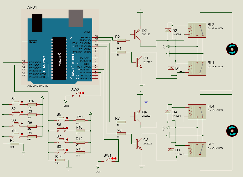
Framed in red working with the code attached

const int buttonPin = A0;       // the number of the pushbutton pin
const int relayPin1 =  13;      // the number of the LED pin for testing
const int relayPin2 =  12;      // the number of the LED pin for testing
const int relayPin3 =  11;
const int relayPin4 =  10;

const int BUTTON1 = 1;
const int BUTTON2 = 2;
const int BUTTON3 = 3;
const int BUTTON4 = 4;

const int BUTTON1LOW = 461;
const int BUTTON1HIGH = 563;
const int BUTTON2LOW = 288;
const int BUTTON2HIGH = 352;
const int BUTTON3LOW = 162;
const int BUTTON3HIGH = 198;
const int BUTTON4LOW = 118;
const int BUTTON4HIGH = 144;

// Variables will change:
int relayState = LOW;         // the current state of the output pin
int buttonState;             // the current reading from the input pin
int lastButtonState = LOW;   // the previous reading from the input pin
int reading;

// the following variables are long's because the time, measured in miliseconds,
// will quickly become a bigger number than can be stored in an int.
long lastDebounceTime = 0;  // the last time the output pin was toggled
long debounceDelay = 50;    // the debounce time; increase if the output flickers

void setup() {
  pinMode(buttonPin, INPUT);
  pinMode(relayPin1, OUTPUT);
  pinMode(relayPin2, OUTPUT);
  pinMode(relayPin3, OUTPUT);
  pinMode(relayPin4, OUTPUT);
  Serial.begin(9600);
}

void loop() {
  // read the state of the switch into a local variable:

  int tmpButtonState = LOW;             // the current reading from the input pin
  int reading = analogRead(buttonPin);

  
  if(reading>BUTTON4LOW && reading<BUTTON4HIGH){
     //Read switch 4
     tmpButtonState = BUTTON4;
   }else if(reading>BUTTON3LOW && reading<BUTTON3HIGH){
     //Read switch 3
     tmpButtonState = BUTTON3;
   }else if (reading > BUTTON2LOW && reading < BUTTON2HIGH) {
    //Read switch 2
    tmpButtonState = BUTTON2;
  } else if (reading > BUTTON1LOW && reading < BUTTON1HIGH) {
    //Read switch 1
    tmpButtonState = BUTTON1;
  } else {
    //No button is pressed;
    tmpButtonState = LOW;

  }

  // check to see if you just pressed the button
  // (i.e. the input went from LOW to a buttonState),  and you've waited
  // long enough since the last press to ignore any noise:

  // If the switch changed, due to noise or pressing:
  if (tmpButtonState != lastButtonState) {
    // reset the debouncing timer
    lastDebounceTime = millis();
  }

  if ((millis() - lastDebounceTime) > debounceDelay) {
    // whatever the reading is at, it's been there for longer
    // than the debounce delay, so take it as the actual current state:
    buttonState = tmpButtonState;
    Serial.println(buttonState, LOW);
  }

  // save the reading.  Next time through the loop,
  // it'll be the lastButtonState:
  lastButtonState = tmpButtonState;

  // set the LED using the state of the button for testing:
  switch (buttonState) {
    case BUTTON1:
      digitalWrite(relayPin1, buttonState > 0);
      break;
    case BUTTON2:
      digitalWrite(relayPin2, buttonState > 0);
      break;
    case BUTTON3:
     digitalWrite(relayPin3, buttonState>0);
     break;
     case BUTTON4:
     digitalWrite(relayPin4, buttonState>0);
     break;
    default:
      digitalWrite(relayPin1, LOW);
      digitalWrite(relayPin2, LOW);
      digitalWrite(relayPin3, LOW);
      digitalWrite(relayPin4, LOW);

  }
}

Framed blue is a supplement that should implement it into existing code

SW2 attached to pin2 (LOW-Manual mode, HIGH-Auto mode)
	if SW2 - LOW -> do Read analog pinA0 (framed in red) and pin3, pin4, pin5, pin6, pin7 not read
	if SW2 - HIGH -> do Read pin3 and pinA0, pin4, pin5, pin6, pin7 not read

SW1 attached to pin3 (LOW-STOP, HIGH-START)
	if SW1 - LOW -> set pin4, pin5, pin6, pin7 and pinA0 to LOW 
		and pin10 to HIGH until pin7 read HIGH then pin10 to LOW 
		and pin12 to HIGH until pin5 read HIGH then pin12 to LOW
	if SW1 - HIGH -> start auto mode

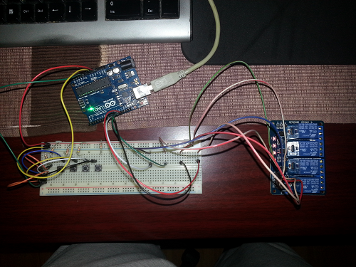
switches LEFT, RIGHT, UP, DOWN is Reed Switch - picture is attached

LEFT 	attached to pin4
RIGHT 	attached to pin5
UP 		attached to pin6
DOWN 	attached to pin7
relay2 	attached to pin13
relay1 	attached to pin12
relay4 	attached to pin11
relay3 	attached to pin10

===== start auto mode ======
SW1 - HIGH -> 
	do pin13 to HIGH until pin4 read HIGH then pin13 to LOW
	then pin11 to HIGH for 3s or pin6 and pin5 read HIGH then 
if pin6 and pin5 read HIGH then pin10 to HIGH until pin7 read HIGH then pin10 to LOW 
	and pin12 to HIGH until pin5 read HIGH then pin12 to LOW
	else
	then pin12 to HIGH until pin5 read HIGH then pin12 to LOW
	then pin11 to HIGH for 3s or pin6 and pin5 read HIGH then 
if pin6 and pin5 read HIGH then pin10 to HIGH until pin7 read HIGH then pin10 to LOW 
	and pin12 to HIGH until pin5 read HIGH then pin12 to LOW
	else
repeat until pin6 and pin5 read HIGH then pin10 to HIGH until pin7 read HIGH then pin10 to LOW 
	and pin12 to HIGH until pin5 read HIGH then pin12 to LOW

images.jpg

20150220_203507.png

20150220_201748.png

20150225_193511.png

Arduino-beginner:
Regards,

Here are trying to explain and re-write an existing project.

You said in Reply #9 that you have only been using the Arduino for a few days. I do wish you would start with something less ambitious. Perhaps just a very small part of this project.

...R

Just as I said in previous posts.
Use Arduino few days.
I've read a lot of stuff in various forums,
I made the first one basic LED blink seed and tasted with already written code.

The code that I used was probably written a long time ago.
I only exercised the conversion resistor value and the button for the analog input.

http://www.raltron.com/cust/tools/voltage_divider.asp

R1 - 47K
R2 - 10k
V -5v

1023/5=204.6

2.5v = 204.6*2.5 = 511.5 +-10% 460.35 --- 562.65 valve for button1

in the original code is not off relays after release button

And the original code that I got worked only with two buttons and two LEDs

When I got the Arduino its purpose was just to try to make something that others had written and that it works. I got the gist of the program and code.

I'm not acquainted with C ++ or programming. This is all new to me.
When I saw how much I have to learn C ++ and weighing electronics. It's not for me in my old age I am learning.
Since I do not know anything about electronics and programming, I decided to purchased Arduino Uno and 4 relays use it for something you do for a long time.

To install it on a lathe for wood as a manual mode via the 4 keys move the knife processing in which direction I want.
Well, that made the first 4 relays and 4 keys and working properly.

When I started thinking about using Arduina in this project, I came to the idea, man to make the automatic mode which I have described in earlier posts.

I tried to try something but we were not successful.

If I fail to do automatic mode Arduino will end up in a shelf as unused.
It is easier than 4 relays to manually move my knife on a lathe than through Arduina.

In any case, thanks for the great help.
Hello everybody

int SW1=3;
int SW2=2;
int LEFT=4;
int RIGHT=5;
int UP=6;
int DOWN=7;
int relay1;
int relay2;
int relay3;
int relay4;
int SW1_Status=0;//default manual mode
int SW2_Status;

int lastButtonState = 0;     // previous state of the button
#define S1  0
#define S2  1
#define S3  2
#define S4  3
#define btnNONE 4
int lcd_key     = 0;
int adc_key_in  = 0;

int read_LCD_buttons()
{
  adc_key_in = analogRead(0);  
  if (adc_key_in < 50)   return S1;  
  if (adc_key_in < 250)  return S2; 
  if (adc_key_in < 450)  return S3; 
  if (adc_key_in <650)  return S4; 
  return btnNONE;  // when all others fail, return this...
}


void setup()
{
  Serial.begin(9600);
  pinMode(SW1,INPUT);
  pinMode(SW2,INPUT);
  pinMode(LEFT,INPUT);
  pinMode(RIGHT,INPUT);
  pinMode(UP,INPUT);
  pinMode(DOWN,INPUT);
  pinMode(relay1,OUTPUT);
  pinMode(relay2,OUTPUT);
  pinMode(relay3,OUTPUT);
  pinMode(relay4,OUTPUT);
}

void loop()
{
  SW2_Status= digitalRead(SW2);
  SW1_Status=digitalRead(SW1);
  if(SW2_Status==0)
  {

  }
  else
  {


  }
  if (SW1_Status != lastButtonState)
  {
    if(SW1_Status==0)
    {
      /*digitalWrite(LEFT,LOW);
       digitalWrite(RIGHT,LOW);
       digitalWrite(UP,LOW);
       digitalWrite(DOWN,LOW);*/
      Serial.println("manual mode is active");
      if(digitalRead(DOWN)==HIGH)
      {
        Serial.println("DOWN key pressed");
        digitalWrite(10,HIGH);
        Serial.println("10 pin is high");
      }
      if(digitalRead(RIGHT)==HIGH)
      {
        Serial.println("Right key pressed");
        digitalWrite(12,HIGH);
        Serial.println("12 pin is high");
      } 
      Serial.println("SW! status is lOW"); 

    }
    else
    {
      Serial.println("Auto mode is active");
      if(digitalRead(4)==HIGH)
      {
        digitalWrite(13,HIGH);
      }
      if((digitalRead(6)==HIGH) &&(digitalRead(5)==HIGH))
      {
        if(digitalRead(7)==HIGH)
        {
          digitalWrite(10,HIGH);

        } 

        if(digitalRead(5)==HIGH)
        {
          digitalWrite(10,LOW);
          digitalWrite(12,HIGH);
        } 
        else
        {
          digitalWrite(12,LOW);
        }


      }

    }
  }
  lastButtonState = SW1_Status;   

  delay(100);
}

Here sample code to test. There lot of confusion in your button selection. Its better you make some table in excel sheet. When in particular state which buttons need to be active & deactive.
Above u have repeated some pins high & low twice.

Reed switch you using as input or output?? because some where you say make up,down,left,right button as low. So clarify Whether u using as input or output.

You no where using analog out pins S0-S4; You using only SW1,Sw2 & posted condition for the up,down,right,left buttons.

You should also mention there roles Here.

I doubt analogWrite(Pin,value); makes those pins active or not. you can check if button status pressed or not depend on analog value read. so there i created function for you.

Arduino-beginner:
Just as I said in previous posts.
Use Arduino few days.
I've read a lot of stuff in various forums,
I made the first one basic LED blink seed and tasted with already written code.

The code that I used was probably written a long time ago.
I only exercised the conversion resistor value and the button for the analog input.

You have not explained why you won't just use digital inputs for your buttons which would make the code much simpler.

And if you insist of trying to do all of this project as one big lump you will find it very difficult. Break it down into several small learning steps (all within this Thread, please.)

If you insist on using resistors and analog inputs start with the shortest possible program that just shows the switch numbers in the Serial Monitor.

...R

I tried to write some code for what we needed.
Somewhat works but not everything.

// set pin numbers:
const int modePin = 2;
const int startPin = 3;
const int leftPin = 4;
const int rightPin = 5;
const int upPin = 6;
const int downPin = 7;
const int relayPin1 =  13;
const int relayPin2 =  12;
const int relayPin3 =  11;
const int relayPin4 =  10;

// variables will change:
int modeState = 0;         // variable for reading the pushbutton status
int startState = 0;
int leftState = 0;
int rightState = 0;
int upState = 0;
int downState = 0;

void setup() {
  // initialize the pin as an output:
  pinMode(relayPin1, OUTPUT);
  pinMode(relayPin2, OUTPUT);
  pinMode(relayPin3, OUTPUT);
  pinMode(relayPin4, OUTPUT);
  // initialize the pushbutton pin as an input:
  pinMode(modePin, INPUT);
  pinMode(startPin, INPUT);
  pinMode(leftPin, INPUT);
  pinMode(rightPin, INPUT);
  pinMode(upPin, INPUT);
  pinMode(downPin, INPUT);
}

void loop() {
  // read the state of the pushbutton value:
  modeState = digitalRead(modePin);
  startState = digitalRead(startPin);
  leftState = digitalRead(leftPin);
  rightState = digitalRead(rightPin);
  upState = digitalRead(upPin);
  downState = digitalRead(downPin);

  // check if the pushbutton is pressed.
  // if it is, the State is HIGH:
  if (modeState == HIGH ) {					// provera statusa prekidaca za izbor moda
    digitalRead(startState);				// procitati taster START za automatski mod
  } else {
    // ubaciti kod za manuelni rad
  }
  if (startState == HIGH) {					// ako je START ukljucen
    delay(1000);							// pauza 10s
    digitalWrite(relayPin1, HIGH);			// aktivirati motor1 u levu stranu
    digitalWrite(relayPin2, LOW);
    digitalWrite(relayPin3, LOW);
    digitalWrite(relayPin4, LOW);
    digitalRead(leftState);					// citanje statusa levog limitera
  }else {
    digitalWrite(relayPin2, LOW);
    digitalWrite(relayPin1, LOW);
    digitalWrite(relayPin3, LOW);
    digitalWrite(relayPin4, LOW);
  }
  
  if (leftState == HIGH) {					// levi limiter aktiviran
    digitalWrite(relayPin1, LOW);			// iskljuci motor1 levu stranu
    delay(300);							// pauza 3s
    digitalWrite(relayPin3, HIGH);		// aktivirati motor2 u gore
    digitalWrite(relayPin2, LOW);
    digitalWrite(relayPin1, LOW);
    digitalWrite(relayPin4, LOW);
    digitalRead(upState);					// citanje statusa gornjeg limitera
  }
  if (upState == HIGH) {					// ako je gornji limiter aktiviran
    digitalWrite(relayPin3, LOW);		// iskljuci
  } else{
    delay(400);						// pauza 4s
    digitalWrite(relayPin2, HIGH);	// aktivirati motor1 u desnu stranu
    digitalWrite(relayPin1, LOW);
    digitalWrite(relayPin3, LOW);
    digitalWrite(relayPin4, LOW);
    digitalRead(rightState);
  } 
}

I will try to amend the code to do what I need.