Besoin d'Aide pour Intégrer un Multiplexeur dans mon Projet Arduino !

Bonjour cher(e)s passionné(e)s d'Arduino et de projets DIY !

Je me lance dans un nouveau défi passionnant : la création d'une Boite a bouton pour mes jeux de simulation. Voici un aperçu rapide de ce que je tente de réaliser :
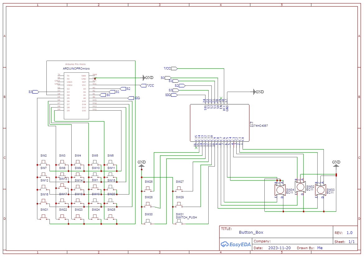
:video_game: Éléments du Projet :

  • Matrice de Boutons 5x5
  • Trois Encodeurs Rotatifs EC11 reliés à un CD74HC4067
  • Six Boutons Indépendants connectés au CD74HC4067
  • Arduino Pro Mini pour la logique de contrôle
  • Utilisation d'un CD74HC4067 pour l'extension d'entrées

:bulb: Objectif Actuel : J'ai adapté le code d'amStudio Lien du code, qui fonctionne parfaitement dans d'autres projets, pour inclure un multiplexeur (CD74HC4067). Cependant, je rencontre un problème : tous les boutons de 24 à 32 semblent être constamment activés

Le code modifier:

//BUTTON BOX
//USE w ProMicro
//Tested in WIN10 + Assetto Corsa
//AMSTUDIO
//20.8.17

#include <Keypad.h>
#include <Joystick.h>
#include <light_CD74HC4067.h>  // Include the library for the multiplexer

#define ENABLE_PULLUPS
#define NUMROTARIES 3
#define NUMBUTTONS 25
#define NUMROWS 5
#define NUMCOLS 5


byte buttons[NUMROWS][NUMCOLS] = {
  { 0, 1, 2, 3, 4 },
  { 5, 6, 7, 8, 9 },
  { 10, 11, 12, 13, 14 },
  { 15, 16, 17, 18, 19 },
  { 20, 21, 22, 23, 24 },
};

struct rotariesdef {
  byte pin1;
  byte pin2;
  int ccwchar;
  int cwchar;
  volatile unsigned char state;
};

rotariesdef rotaries[NUMROTARIES]{
  //Ce n'est pas les bon pin je ne sais pas comment les declarer. ils sont relier au CD74HC4067
  { 0, 1, 24, 25, 0 },
  { 2, 3, 26, 27, 0 },
  { 4, 5, 28, 29, 0 },

};

#define DIR_CCW 0x10
#define DIR_CW 0x20
#define R_START 0x0

#ifdef HALF_STEP
#define R_CCW_BEGIN 0x1
#define R_CW_BEGIN 0x2
#define R_START_M 0x3
#define R_CW_BEGIN_M 0x4
#define R_CCW_BEGIN_M 0x5
const unsigned char ttable[6][4] = {
  // R_START (00)
  { R_START_M, R_CW_BEGIN, R_CCW_BEGIN, R_START },
  // R_CCW_BEGIN
  { R_START_M | DIR_CCW, R_START, R_CCW_BEGIN, R_START },
  // R_CW_BEGIN
  { R_START_M | DIR_CW, R_CW_BEGIN, R_START, R_START },
  // R_START_M (11)
  { R_START_M, R_CCW_BEGIN_M, R_CW_BEGIN_M, R_START },
  // R_CW_BEGIN_M
  { R_START_M, R_START_M, R_CW_BEGIN_M, R_START | DIR_CW },
  // R_CCW_BEGIN_M
  { R_START_M, R_CCW_BEGIN_M, R_START_M, R_START | DIR_CCW },
};
#else
#define R_CW_FINAL 0x1
#define R_CW_BEGIN 0x2
#define R_CW_NEXT 0x3
#define R_CCW_BEGIN 0x4
#define R_CCW_FINAL 0x5
#define R_CCW_NEXT 0x6

const unsigned char ttable[7][4] = {
  // R_START
  { R_START, R_CW_BEGIN, R_CCW_BEGIN, R_START },
  // R_CW_FINAL
  { R_CW_NEXT, R_START, R_CW_FINAL, R_START | DIR_CW },
  // R_CW_BEGIN
  { R_CW_NEXT, R_CW_BEGIN, R_START, R_START },
  // R_CW_NEXT
  { R_CW_NEXT, R_CW_BEGIN, R_CW_FINAL, R_START },
  // R_CCW_BEGIN
  { R_CCW_NEXT, R_START, R_CCW_BEGIN, R_START },
  // R_CCW_FINAL
  { R_CCW_NEXT, R_CCW_FINAL, R_START, R_START | DIR_CCW },
  // R_CCW_NEXT
  { R_CCW_NEXT, R_CCW_FINAL, R_CCW_BEGIN, R_START },
};
#endif

byte rowPins[NUMROWS] = { 5, 6, 7, 8, 9 };
byte colPins[NUMCOLS] = { 10, 13, 14, 15, 4 };

Keypad buttbx = Keypad(makeKeymap(buttons), rowPins, colPins, NUMROWS, NUMCOLS);

Joystick_ Joystick(JOYSTICK_DEFAULT_REPORT_ID,
                   JOYSTICK_TYPE_JOYSTICK, 40, 0,  // Change the number of buttons to 40
                   false, false, false, false, false, false,
                   false, false, false, false, false);

CD74HC4067 mux(A1, A2, A3, 3);  // Create a CD74HC4067 object with control pins and common pin

void setup() {
  Joystick.begin();
  rotary_init();
}

void loop() {

  CheckAllEncoders();

  CheckAllButtons();
}

void CheckAllButtons(void) {
  if (buttbx.getKeys()) {
    for (int i = 0; i < LIST_MAX; i++) {
      if (buttbx.key[i].stateChanged) {
        switch (buttbx.key[i].kstate) {
          case PRESSED:
          case HOLD:
            Joystick.setButton(buttbx.key[i].kchar, 1);
            break;
          case RELEASED:
          case IDLE:
            Joystick.setButton(buttbx.key[i].kchar, 0);
            break;
        }
      }
    }
  }

  // Add this code to read the 16 channels of the multiplexer and send them to the joystick
  for (int i = 0; i < 16; i++) {
    int val = analogRead(i);
    Joystick.setButton(i + 24, val);
  }
}


void rotary_init() {
  for (int i = 0; i < NUMROTARIES; i++) {
    pinMode(rotaries[i].pin1, INPUT);
    pinMode(rotaries[i].pin2, INPUT);
#ifdef ENABLE_PULLUPS
    digitalWrite(rotaries[i].pin1, HIGH);
    digitalWrite(rotaries[i].pin2, HIGH);
#endif
  }
}


unsigned char rotary_process(int _i) {
  unsigned char pinstate = (digitalRead(rotaries[_i].pin2) << 1) | digitalRead(rotaries[_i].pin1);
  rotaries[_i].state = ttable[rotaries[_i].state & 0xf][pinstate];
  return (rotaries[_i].state & 0x30);
}

// Add this code to check the rotation of the encoders and send the signals to the joystick
void CheckAllEncoders(void) {
  for (int i = 0; i < NUMROTARIES; i++) {
    unsigned char result = rotary_process(i);
    if (result == DIR_CCW) {
      Joystick.setButton(rotaries[i].ccwchar, 1);
      delay(50);
      Joystick.setButton(rotaries[i].ccwchar, 0);
    };
    if (result == DIR_CW) {
      Joystick.setButton(rotaries[i].cwchar, 1);
      delay(50);
      Joystick.setButton(rotaries[i].cwchar, 0);
    };
  }
}

:pray: Merci d'Avance ! Merci à tous ceux qui prendront le temps de jeter un œil à mon problème. Vos idées créatives et vos connaissances sont inestimables pour moi en ce moment. N'hésitez pas à me poser des questions ou à me faire part de vos suggestions.

Happy Coding ! :rocket::sparkles:

quel arduino ?

juste pour bien comprendre

une matrice 5x5 ça fait 25 boutons, pourquoi NUMBUTTONS vaut 24 ?
pourquoi la dernière ligne du tableau n'a pas 5 éléments ?

Pour le projet c'est un Arduino Pro Micro Atmega32u4 USB 5V 16MHz

C'est une erreur de ma part j'ai modifié

vous pouvez mettre un schéma de câblage et d'alimentation ? (et le code corrigé)

J'espère que mon schéma est lisible.

Tes switches 23, 33 et 34 me semblent bizarrement connectés.
As-tu testé ce qui est mis en contact lorsque tu enfonces le bouton poussoir ? Ca te montrera ce que tu dois relier à un GPIO et au GND. Il te faut aussi une résistance de pullup par bouton poussoir. Voir ici un exemple :

vous voulez dire 32?

à mon avis ce ne sont pas des switch mais les encodeurs rotatifs

J'espère que mon schéma est lisible.

Tout à fait !

Les 3 éléments EX11 repérés SW32, SW33 et SW34 sur le schéma
image

sont des encodeurs (bornes A, B et C) combinés à des interrupteurs (bornes DE et E)
EC11-VER-20-CIR

En reliant C et D à ma masse il faut des pull up sur A,B et E

Attention

  1. Le schéma montre au niveau de SW34 une connection entre A, B, C (points rouges) donc une mise a la masse permanente de A et B , donc des entrées C4 et C5 du multiplexeur
    image

  2. I faut relier à la masse l'entrée EN d'un HC4067 pour l'activer

oui c'est bien des Encodeurs

il y a une raison d'utiliser cette usine à gaz au lieu d'un io expander?

La seul raison c'est les composant que j'ai sous la main apres si c'est vraiment plus simple je suis ouvert je vais regarder comment fonctionne un io expander.
Merci a tous de vos reponses

voir ce genre de composant sur Ali mais il en existe une multitude suivant l'application désirée. il a l'avantage de libérer les io du micro avec une simple utilisation du TWI

https://fr.aliexpress.com/item/1005005905786832.html?spm=a2g0o.productlist.main.11.1b125df68JlVSl&algo_pvid=56ac6f02-0582-42b9-b390-122e0728797a&aem_p4p_detail=202311251215482931990701885080006031116&algo_exp_id=56ac6f02-0582-42b9-b390-122e0728797a-5&pdp_npi=4%40dis!EUR!1.17!1.17!!!8.92!!%4021038e8317009433485041026e3bc2!12000034791396794!sea!FR!0!AB&curPageLogUid=aefAvFtTmiHa&search_p4p_id=202311251215482931990701885080006031116_6

Excellente raison :wink:

C'est un module avec un PCF8575
"le grand père PCF8575 est un peu dépassé"
Le MCP23016 est un meilleur choix.

  1. il est 16 bits au lieu de 8bits pour le PCF. (il existe une variante 8 bits : MCP23008)

  2. C'est un "Vrai" IO qui fonctionne en mode entrée ou en mode sortie.
    Le PCF ne travaille directement qu'en mode sortie, en mode entrée c'est tout un bazar à gérer avec des interruptions suivies d'un polling.

Salut la communauté Arduino !

J'ai mis la main sur un PCF8575 et j'ai epuré le code d'origine pour ne garder que ma précieuse matrice de boutons. Ça marche nickel jusqu'ici.

#include <Keypad.h>
#include <Joystick.h>

#define NUMROWS 4
#define NUMCOLS 4

byte buttons[NUMROWS][NUMCOLS] = {
  { 1, 2, 3, 4 },
  { 5, 6, 7, 8 },
  { 9, 10, 11, 12 },
  { 13, 14, 15, 16 },

};

byte rowPins[NUMROWS] = { 6, 7, 8, 9 };
byte colPins[NUMCOLS] = { 2, 3, 4, 5 };

Keypad buttonBox = Keypad(makeKeymap(buttons), rowPins, colPins, NUMROWS, NUMCOLS);

Joystick_ Joystick(JOYSTICK_DEFAULT_REPORT_ID,
                   JOYSTICK_TYPE_JOYSTICK, 32, 0,
                   false, false, false, false, false, false,
                   false, false, false, false, false);

void setup() {
  Joystick.begin();
}

void loop() {
  checkButtons();
}

void checkButtons() {
  if (buttonBox.getKeys()) {
    for (int i = 0; i < LIST_MAX; i++) {
      if (buttonBox.key[i].stateChanged) {
        switch (buttonBox.key[i].kstate) {
          case PRESSED:
          case HOLD:
            Joystick.setButton(buttonBox.key[i].kchar, 1);
            break;
          case RELEASED:
          case IDLE:
            Joystick.setButton(buttonBox.key[i].kchar, 0);
            break;
        }
      }
    }
  }
}

Cependant, j'ai besoin de vos lumières pour intégrer correctement ce fameux PCF8575. J'ai tenté quelques approches

#include <Wire.h>
#include <Keypad.h>
#include <Joystick.h>

#define NUMROWS 4
#define NUMCOLS 4

// Adresse I2C du PCF8575
#define PCF8575_ADDRESS 0x20

byte buttons[NUMROWS][NUMCOLS] = {
  { 1, 2, 3, 4 },
  { 5, 6, 7, 8 },
  { 9, 10, 11, 12 },
  { 13, 14, 15, 16 },
};

byte rowPins[NUMROWS] = { 6, 7, 8, 9 };
byte colPins[NUMCOLS] = { 0, 1, 2, 3 };  // Les pins P0 à P3 du PCF8575

Keypad buttonBox = Keypad(makeKeymap(buttons), rowPins, colPins, NUMROWS, NUMCOLS);

Joystick_ Joystick(JOYSTICK_DEFAULT_REPORT_ID,
                   JOYSTICK_TYPE_JOYSTICK, 32, 0,
                   false, false, false, false, false, false,
                   false, false, false, false, false);

void setup() {
  Wire.begin();  // Initialiser la communication I2C
  Joystick.begin();
}

void loop() {
  checkButtons();
}

void checkButtons() {
  if (buttonBox.getKeys()) {
    for (int i = 0; i < LIST_MAX; i++) {
      if (buttonBox.key[i].stateChanged) {
        switch (buttonBox.key[i].kstate) {
          case PRESSED:
          case HOLD:
            Joystick.setButton(buttonBox.key[i].kchar, 1);
            break;
          case RELEASED:
          case IDLE:
            Joystick.setButton(buttonBox.key[i].kchar, 0);
            break;
        }
      }
    }
  }
}

mais pas de resultat positif
Le cablage avec le pcf8575

Merci d'avance pour vos talents !

La librairie Keypad ne fonctionne pas avec un IOExpander il me semble.
On doit sans doute trouver des librairies dédiés.

Voir peut-être ici

Bonjour fdufnews

Je connais pour PCF8574, c'est la bibliothèque I2CKeyPad.

Cordialement
jpbbricole

Je viens de tester avec la bibliotheque I2Ckeypad avec le pcf8575 sa fontionne


#include <Key.h>
#include <Keypad.h>
#include <Keypad_I2C.h>

#define I2CADDR 0x20  // Set the Address of the PCF8574

const byte ROWS = 4;  // Set the number of Rows
const byte COLS = 4;  // Set the number of Columns

// Set the Key at Use (4x4)
char keys[ROWS][COLS] = {
  { '1', '2', '3', 'A' },
  { '4', '5', '6', 'B' },
  { '7', '8', '9', 'C' },
  { '*', '0', '#', 'D' }
};

// define active Pin (4x4)
byte rowPins[ROWS] = { 0, 1, 2, 3 };  // Connect to Keyboard Row Pin
byte colPins[COLS] = { 4, 5, 6, 7 };  // Connect to Pin column of keypad.

// makeKeymap (keys): Define Keymap
// rowPins:Set Pin to Keyboard Row
// colPins: Set Pin Column of Keypad
// ROWS: Set Number of Rows.
// COLS: Set the number of Columns
// I2CADDR: Set the Address for i2C
// PCF8574: Set the number IC
Keypad_I2C keypad(makeKeymap(keys), rowPins, colPins, ROWS, COLS, I2CADDR, PCF8575);

void setup() {
  Wire.begin();                    // Call the connection Wire
  keypad.begin(makeKeymap(keys));  // Call the connection
  Serial.begin(9600);
}
void loop() {

  char key = keypad.getKey();  // Create a variable named key of type char to hold the characters pressed

  if (key) {              // if the key variable contains
    Serial.println(key);  // output characters from Serial Monitor
  }
}

donc j'ai modifier mon code

#include <Wire.h>
#include <Keypad_I2C.h>  // Inclure la bibliothèque Keypad_I2C
#include <Joystick.h>

#define I2CADDR 0x20  // Adresse I2C du PCF8575

const byte ROWS = 4;
const byte COLS = 4;

byte buttons[ROWS][COLS] = {
  { 1, 2, 3, 4 },
  { 5, 6, 7, 8 },
  { 9, 10, 11, 12 },
  { 13, 14, 15, 16 },
};


byte rowPins[ROWS] = { 0, 1, 2, 3 };
byte colPins[COLS] = { 4, 5, 6, 7 };

Keypad_I2C keypad(makeKeymap(buttons), rowPins, colPins, ROWS, COLS, I2CADDR, PCF8575); 

Joystick_ Joystick(JOYSTICK_DEFAULT_REPORT_ID,
                   JOYSTICK_TYPE_JOYSTICK, 32, 0,
                   false, false, false, false, false, false,
                   false, false, false, false, false);

void setup() {
  Wire.begin();
  Joystick.begin();
}

void loop() {
  checkButtons();
}

void checkButtons() {
  if (keypad.getKeys()) {
    for (int i = 0; i < LIST_MAX; i++) {
      if (keypad.key[i].stateChanged) {
        switch (keypad.key[i].kstate) {
          case PRESSED:
          case HOLD:
            Joystick.setButton(keypad.key[i].kchar, 1);
            break;
          case RELEASED:
          case IDLE:
            Joystick.setButton(keypad.key[i].kchar, 0);
            break;
        }
      }
    }
  }
}

mais je suis au même point. Je vais me mettre au tricot peut être que j'aurais plus de succès

T'aurais pas oublié quelque chose dans le setup()

Un grand merci c'est bon sa fonction

#include <Wire.h>
#include <Keypad_I2C.h>  // Inclure la bibliothèque Keypad_I2C
#include <Joystick.h>

#define I2CADDR 0x20  // Adresse I2C du PCF8575

const byte ROWS = 4;
const byte COLS = 4;

byte buttons[ROWS][COLS] = {
  { 1, 2, 3, 4 },
  { 5, 6, 7, 8 },
  { 9, 10, 11, 12 },
  { 13, 14, 15, 16 },
};

// Définir les broches actives (à adapter en fonction du câblage avec le PCF8575)
byte rowPins[ROWS] = { 0, 1, 2, 3 };
byte colPins[COLS] = { 4, 5, 6, 7 };

Keypad_I2C keypad(makeKeymap(buttons), rowPins, colPins, ROWS, COLS, I2CADDR, PCF8575);  // Utiliser Keypad_I2C

Joystick_ Joystick(JOYSTICK_DEFAULT_REPORT_ID,
                   JOYSTICK_TYPE_JOYSTICK, 32, 0,
                   false, false, false, false, false, false,
                   false, false, false, false, false);

void setup() {
  Wire.begin();
  Joystick.begin();
  keypad.begin(makeKeymap(buttons));
}

void loop() {
  checkButtons();
}

void checkButtons() {
  if (keypad.getKeys()) {
    for (int i = 0; i < LIST_MAX; i++) {
      if (keypad.key[i].stateChanged) {
        switch (keypad.key[i].kstate) {
          case PRESSED:
          case HOLD:
            Joystick.setButton(keypad.key[i].kchar, 1);
            break;
          case RELEASED:
          case IDLE:
            Joystick.setButton(keypad.key[i].kchar, 0);
            break;
        }
      }
    }
  }
}