What is the range, the span of voltage You want to measure?
Reading mV can be done by almost every ADC. One important piece is a precise reference voltage.
A thing to consider is to look at the spec sheets of the ADC's. That the ADC may be 24 bits how many bits does the ADC send to the Arduino and will you be using a UNO, an 8 bit machine?
@idahowalker yes, it will be 8-bit.i considered the stm32 "bluepill" chip, but i think ill stick to the atmega 328p. adc doesnt care about the arduinos limitations speed wise (to a point).
@railroader this device is powered by a 3.7v lipo battery. could i use something like the TI REF3012?
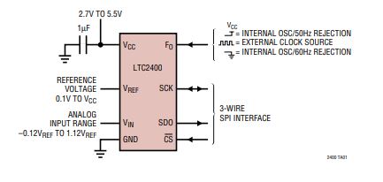
the ltc2400 has support for a voltage refrence input. i'm unsure yet of the range, but i think it will be safe to say 0mV to maybe 600mV?
Measuring voltages from 0 to 600 mV doesn't call for any extrodinary ADC. The 10 bit ADC in an UNO provides 512 levels.
The voltage powering the controller is not important. I have no knowledge about those components and I don't spend time on Googling.
A usual mistake made by lots of people. The cheep thermometers show decimals of degrees but are often off by 1 or even 2 degrees. A small change is probably rather correct, like an AC component but the DC level is inaccurate.
Okey. You look like having knowledge about the need of accurazy.
Every project should be deloped from bottom to top. What is the bottom line requirements and what will that call for? Too often developers starts in the other end, looking for the highest sensor quality, spending lots of uneccessary money.
So you need accuracy of 100uV and resolution of 10uV? What is the application? What voltage reference and what op-amp do you plan to use to achieve this level of accuracy? How will you design your circuit to be noise-free to those levels?
ok. in the simplest terms possible i want to measure the voltage generated by this project: uCurrent
its used for measuring precision current.
i am creating a very modified version of this, but that should show what i need it to-do.
since it is designed with shunts of
1mV/mA
1mV/µA
1mV/nA
thats where i get my need for 0-600mv with maximum of 0-800mv
since its measuring precision current, i would like to make this as accurate as possible, hence i want at least a measuring/precision capability as explained:
i.e. resolution of 500.00mV measurement capability, with it being accurate to 500.0mV or better.
am i correct in this thinking? i will admit i'm rather new to analog design (eeng student, but haven't taken analog courses yet)
@paulrb i will be using precision op-amps (set of MAX4239AUT)(0.1uV offset), with precision resistors. the arduino is optically isolated, the measurment side is powered using battery, and the whole thing will live inside a small alluminum enclosure.
i dont expect to get the noise right on the first board design though, but i will try.
i.e. resolution of 500.00mV measurement capability, with it being accurate to 500.0mV or better.
This does not make sense. If you say resolution of 500mV or 500.0mV or 500.00mV that's the same thing. I think what you mean to say is a resolution of 0.01mV. In other words the ability to distinguish 499.99mV from 500.00mV from 500.01mV. Correct?
For that level of resolution, you will need 600 / 0.01 = 60,000 distinct values from your adc. That's 16 bits resolution.
that is 100% correct. my bad for bad explanation. however, i'd like to have a bit more room, so i would like to be able to go up to 800mv, so 800/0.01 = 80,000
16-bit is a definite option. thanks for showing the math formula.
from the adc (of the 3 originally mentioned) that i'm looking at, the cost between a 16-bit and 24-bit are negligible. (of the two mentioned below, one is spi and the other is i2c. spi optocouplers are cheaper than i2c, so cost can be made up there).
i'm looking at the 24-bit ltc2400 as the most viable option (10$), vs something like the ads1115 which comes in at (6$)- which does not have an onboard option for a precision voltage refrence.
in my first post i mentioned 3 options that are arduino compatable. am i missing any other viable options?
ok thanks. i think i've decided to go with the 24-bit ltc2400
as for op-amps, i will be using precision op-amps (set of MAX4239AUT)(0.1uV offset), with precision resistors. the arduino is optically isolated, the measurment side is powered using battery, and the whole thing will live inside a small alluminum enclosure.
the battery is a lipo, 3.7v
as for how to connect the op-amps output to the adc, i have no idea, as i am admitedly rather new to the world of analog design. see below as to how i currently have it connected.
i plan on measuring low voltage ac (isolated), and dc signals all of which have the potential for positive and negative voltages. how would i account for this on the ADC connection? i know that ADCs don't necessarily like negative voltages. will this even be a problem?
here are the main 3 parts of the analog side. +3.7v goes to +Vbat, -3.7v goes to -Vbat, and im generating a virtual ground.