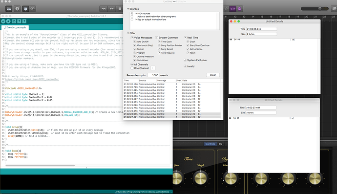
For anyone building a MIDI controller, the above is a must!
It also includes the MIDIUSB library, if your board supports a native USB.
I have however stumbled on a slight issue regarding using encoders with Arturia's Analog Lab VST via GarageBand.
I've read the ReadMe and played with the sketch many times, but the best i can get the encoders and the activated Analog Lab controls is;
1 click/detent C/W = 1 increment increase.
1 click CC/W = 1 increment decrease, next click CC/W = another 2 incrment decrease, next click CC/W = another 1 increment decrease.
So C/W works, but CC/W is 1,2,1,2,1,2 and so on.
I did find this regarding Arturia's MiDI controller, which may have some bearing on this issue;
Technical stuff for those who want to know more
RELATIVE MODE
Relative mode means that the encoders send MIDI messages that can increment or decrement a parameter without
there being jumps in the values. This allows for smooth operation and allows for greater interaction in applications that
support this type of MIDI data. Example:
If the encoders are set to RELATIVE 1 (using the free MIDI CONTROL CENTER software), the encoders will send a stream of
MIDI messages with data values of 65-67 when turned clockwise and will send a string of MIDI message 63-61 when turned
counter clockwise. The faster you turn the encoder, the higher or lower the data value. Relative 2 and Relative 3 modes
are similar in operation but send different values.
/*
This is an example of the "RotaryEncoder" class of the MIDI_controller library.
Connect the A and B pins of the encoder to 2 interrupt pins (2 and 3). It's recommended to use 100nF capacitors between the A and B pins and ground.
Connect the common (C) pin to the ground. Pull-up resistors are not necessary, since the internal ones will be used.
Map the control change message 0x14 to the right control in your DJ or DAW software, and select 'relative' instead of 'absolute'.

If you are using a jog wheel, use JOG, if you are using a normal encoder (for normal controls like EQ or volume etc.) use NORMAL_ENCODER.
If you have strange results in your software, try another relative mode: ADD_64, SIGN_BIT or POS1_NEG127.
If the control works, but it goes in the wrong direction, swap the pins A and B of the encoder (physically, or when creating the
RotaryEncoder member).

If you are using a Teensy, make sure you have the USB type set to MIDI.
If you are using an Arduino Uno or Mega, use the HIDUINO firmware for the ATmega16U2.


Written by tttapa, 21/08/2015
https://github.com/tttapa/MIDI_controller
*/

#include <MIDI_controller.h>

const static byte Channel = 1;
const static byte Controller1 = 0x14;
const static byte Controller2 = 0x15;

//________________________________________________________________________________________________________________________________

RotaryEncoder enc1(5,6,Controller1,Channel,1,JOG,ADD_64); // Create a new instance of the class 'RotaryEncoder', called 'enc', on pin 2 and 3, controller number 0x14, on channel1, no change in speed (speed is multiplied by 1), it's used as a Jog wheel, and the mode is set to POS1_NEG127.
RotaryEncoder enc2(7,8,Controller2,Channel,1,JOG,ADD_64);

//________________________________________________________________________________________________________________________________

void setup(){
  USBMidiController.blink(13);  // flash the LED on pin 13 on every message
  USBMidiController.setDelay(15);  // wait 15 ms after each message not to flood the connection
  delay(1000); // Wait a second...
}

//________________________________________________________________________________________________________________________________

void loop(){
  enc1.refresh();
  enc2.refresh();
}
Can anyone offer any thoughts so 1 click/detent = 1 increment + & -?
Dizzwold.
