Hello,
A couple of months ago I got my Arduino Starter Kit and started learning about electronics, and then experimenting with a custom HA system.
Among the things I wanted to automate were the lights and some other switches in my apartment. But being a "software guy" I made a quick test setup and went straight for the software part. Now that I've got that mostly figured out, I'd like to do the hardware part right, and need some help from someone who is a bit more experienced.
My goal is to control the switches and know their current state, but without interfering with normal (manual) use and using specialized switches.
You can see my initial test setup here (- YouTube). It uses a servo with some fixed strings, and I planned to put a custom made switch beneath one of the "teeth". Input to the switch would be the same + wire going into the servo, and output would be a "sensing" wire, so I'd need 4 wires per switch. Using nylon/plastic strings would make it more reliable, but I still don't like it too much.
And here's what I'm aiming for:
- place wires into walls
- use SFTP network cables (8 wires per cable)
- use as few wires as possible
- use wires as short as possible (7m max, though I've tested the servo with 15m and it works)
- modify existing switches
- automation must not interfere with normal operation of the switch
- add a component to mechanically flip the switch on and off
- add a component to sense the state of the switch
- components should be reliable and not malfunction (repairing would be hard because they're going into brick/block and mortar walls)
- components should be as small as possible, to avoid digging into the walls too much
- safety - power used for the light switch (220V AC) must not interfere with automation components. This is my major concern. It might be complete nonsense, but I'm mostly worried about induction and the whole thing going up in flames or electrocuting someone. Please advise on this.
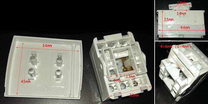
You can see the layout and size of the light switch I'm using in the attached photo.
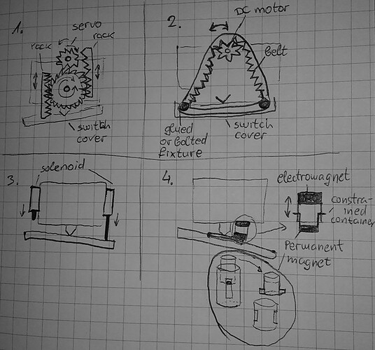
And here are some ideas I've thought of, but I'm unsure if and/or how they can be implemented safely. There's an attached drawing showing every one of them.
-
Glue the servo at the same place as in the test, but instead of the cross attachment and strings use a gear, pinion and two racks (see Rack and pinion - Wikipedia). Trouble here is making the gears and racks, because they'd have to have just right teeth and be pretty small, and I'm worried about their strength and cost if I go with e.g. 3D printing.
-
Use a DC motor glued at the same place as in the test with a toothed (conveyor?) belt instead of the strings. The belt would be tight, so manually flipping the switch would turn the motor as well, but unlike the servo it won't break because it's not constrained. I've disassembled one of my micro servos and found a small DC motor inside, approximately 7x12mm, but I'm unsure if I can make it spin both ways, as well as if it's strong enough. Trouble here is making the belt, because it too will have to be both small and strong.
-
Use 2 solenoids, one on each side of the switch. Trouble with these is they'd have to be pretty small, which means I'd have to make them from scratch, and they'd have to pack enough of a punch with only 5V they're getting.
-
This is something that might not even be possible, but seems logical to me at the time. Glue a permanent magnet at one end of the switching lever and place an electromagnet on the base beneath it. By controlling the polarity of the electromagnet make the two attract or repel to flip the switch. If this is possible the trouble would be getting magnets small enough and making the attraction/repulsion strong enough to filp the switch.
Thanks in advance for all of your suggestions and comments, I hope I haven't written too much nonsense ![]()
UPDATE 1
After receiving a couple of replies I see that providing some more info would be in order:
The device I'm seeking advice on how to build here is not even close to being my whole project, but just a tiny part of it, which is important and currently troubling me the most. The test setup shown in the video is just an experiment to quickly test driving a switch using an Arduino and my mini command language.
I am aware of the approaches most people take when automating lights, similar switches and even wall sockets, but they aren't applicable or desired in my case. Those include:
- off-the-shelf switches with built in relays and controllers... (existing solutions, like X10 and similar)
- other replacement switches (e.g. touch switches combined with relays)
- relays controlling the mains line to the switch or the appliance. Correct manual operation of the switch is most important, automation should not hinder it in any way. The physical (up and down) state of the switch should unambiguously reflect the on/off state of the appliance
- using a separate microcontroller setup per switch (way to large and expensive)
So that's why I'm trying to find an alternative. Mechanical is just the one that came to me naturally and I'm trying to find the best solution using it, but I'm willing to do it another way.
UPDATE 2
Correct manual operation of the switch is most important, automation should not hinder it in any way. The physical (visible) state of the switch (up or down) must at all times reflect the on/off state of the appliance. For example, if you see the switch across the room is down then the appliance it's controlling must be OFF. And vice-verse, if the appliance is off then the switch will be down.
More about the project:
My project v1 consists of a Raspberry Pi B reading from and writing to an USB "home" device (Arduino Uno R3) via custom serial command language.
Apart from controlling the "home" device, the RPi is also currently acting as a remote storage, UPnP/DLNA media server and renderer, and Bluetooth speaker, and will be more in the future.
The "home" device v1 I've planned and am building is wired through a MUX Shield to multiple indoor and outdoor sensors (temp, humidity, light, wind/draft, motion, door and window state, switch state), indoor switches (light, water heater, ventilator, door buzzer) and some more. In and v2 I plan on adding some controllers (thermostat, AC unit) and sensors (mailbox full, doorbell camera), and so on...
So, you can see that this is not a novelty project or a toy (I get over those in a couple of days), but something I think would be useful and fun to build, as well as a great learning opportunity.


