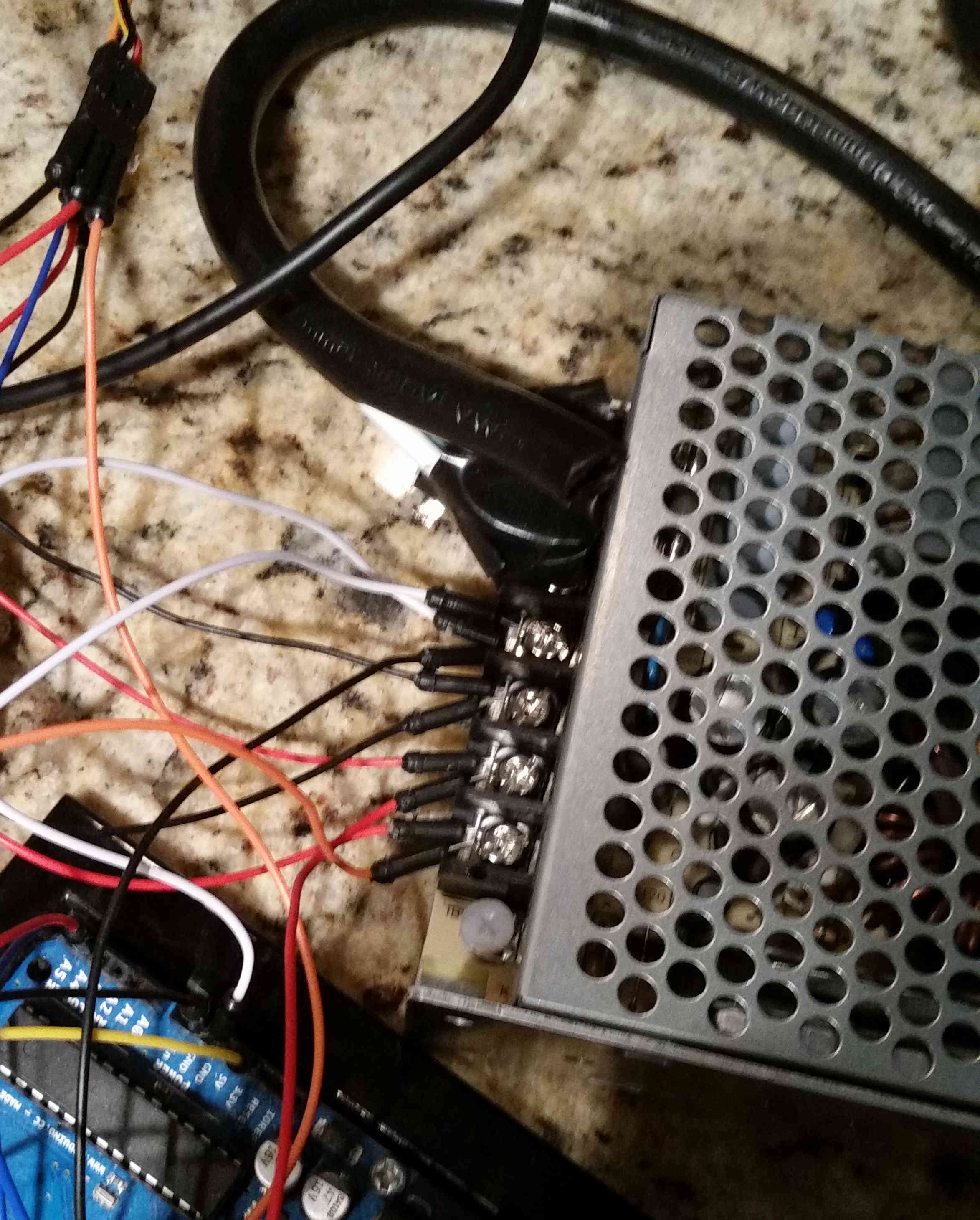
I'm new to Arduino and Electronics in general. I'm using an external power supply to power several servos, and everything is working fine, but I'm looking at this and can't help but think there has got to be a better way to do this. It's ugly both aesthetically and it offends my technical sense (as a programmer lol!). Every time I want to add a new servo I have to loosen the screws and corral all the wires back in there again. It just seems wrong.
Any recommendations for a better way? Any input would be greatly appreciated! Pic attached.
Look for terminal strips or barrier blocks. You can get them with long strips of terminals to join multiple screw terminals together to make a common buss. I have a long barrier block in my irrigation control box and join multiple AC power connections to a common AC power feed.
Google the names and look at photos till you see something you like.
Servos only?
An Adafruit PCA9685 breakout board has pinheaders to plug in 16 servos (see second small picture).
And one power connector (for all 16 servos).
Clones on ebay.
Leo..
Wawa's example is valid but would require changing your code to now use the protocol required by the board.
If you want to keep your code the same and simply modify the wire requirements, you could go with a prototype board. We ran 18 servos to 18 pints on our Arduino Mega with a common power bus. Then the servos could simply plug in using the stock plug ends.
I'll see if I can find a pic.
Edit: Even better, here is the thread where I posted a bunch of pics.
Note that the voltage regulator that I used in that version turned out to be inadequate for the total draw of all the servos I ran. It worked well enough most of the time for making the hexapod walk, but if you added any load or did any large movements, the servos would brown out and fail to support the structure.
But here is the one pic from that thread that I am talking about.
The 2 orange wires at the bottom are the power for all 18 servos.
Yeah, that's starting to look like a real world fritzing gone horribly wrong. Using a terminal bar would be the cleanest, using a single common wire from the PS. As a bonus, it keeps you away from the exposed mains terminals on that PS.
Also, those metal terminal clamps in your power supply are normally for clamping down multi-strand wire....... usually not for clamping a solid pin from an arduino jumper wire.
Life will be simpler if you add something like this to the terminal strips. Make sure to match the dimensions of the jumpers to the strip. Or, just make your own with short lengths of daisy-chained wire.
For temporary connections of temporary projects, I use speaker spring terminals to break out an easy connection point from the power supply's screw terminals.
INTP:
For temporary connections of temporary projects, I use speaker spring terminals to break out an easy connection point from the power supply's screw terminals.
Nice idea! If you need a lot of connections you can roll your own.
That is just a kickass set of options, y'all, thanks! Everything makes tons of sense except one thing I can't quite figure out from google--what is the difference between a terminal strips and a barrier block?
Do you just attach the top two screws to power and the rest are in line with that? Or do I need the thing dougp suggested? I'm a little confused by that object.
rastoboy:
That is just a kickass set of options, y'all, thanks! Everything makes tons of sense except one thing I can't quite figure out from google--what is the difference between a terminal strips and a barrier block?
Do you just attach the top two screws to power and the rest are in line with that? Or do I need the thing dougp suggested? I'm a little confused by that object.
A barrier block is a terminal strip with barrier ridges between each screw pair. Keeps any stray wire strands from getting together.
Usually, on barrier strips, I use the manufactured jumpers to connect the power and ground wires to the needed expansions on opposite ends of the barrier strip. Signal and control wires go in the middle. IF the installation is permanent, I use crimp terminals on the wires and then attach them with the screws on the barrier strip.
Here's a short video which may answer some of your questions. The main feature of these is that you can have as many or as few as you need for the job. Many others besides A-D make these commodity items. Some connect adjacent blocks with the screw type shown in the video, others use a comb-looking piece which fits into successive terminals and shorts them all together - this kind eliminates the spring attachment.
They all mount on a DIN rail. These are widely used in industrial control equipment.
I think the advice I gave in post#2 is still the best.
Servos are plug and play and hardware driven, so no load on the Arduino once a servo position is set.
One power/ground wire per 16 servos to the supply.
Two control wires (I2C) and 5volt/ground to the Arduino for (theoretically) up to 960 servos.
Leo..
Looking at all these, I think some may be more appropriate for some situations than others. I feel like I'm on the right track to making good decisions now