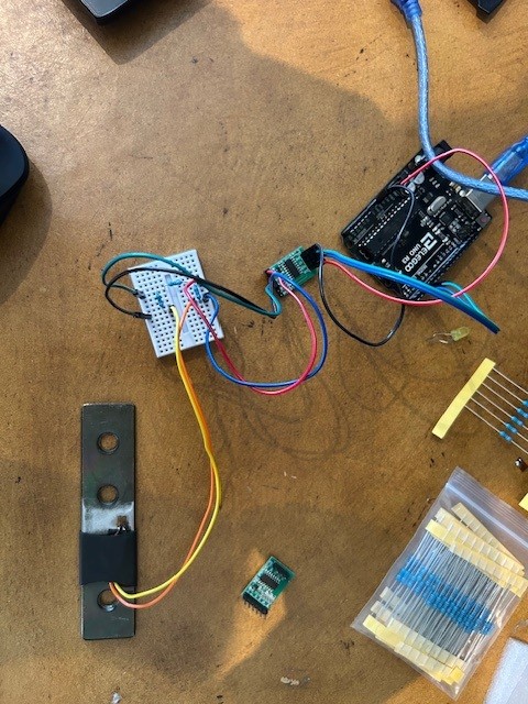
I am working on a personal project to learn a bit more about strain gauges and how to connect them. I currently have a BF350 strain gauge attached to a metal bracket for a desk. I have created a Wheatstone bridge using 330-ohm resistors arranged as shown. I am using a HX711 load cell amplifier and an Elegoo Uno R3 board. Please see the physical wiring below.
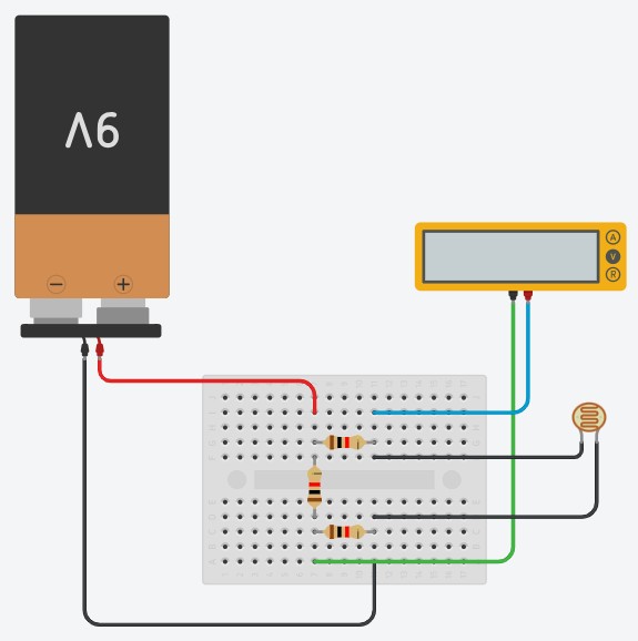
I tested this circuit on TinkerCAD (albeit without the HX711) and the colors of the wires are all the same. For the HX711, red is E+, black is E-, blue is A+, and green is A-. The TinkerCAD is shown below with a photoresistor in place for the gauge.
My code is shown below (I hope that is formatted correctly).
#include "HX711.h"

const int LOADCELL_DOUT_PIN = 3;
const int LOADCELL_SCK_PIN = 2;

HX711 scale;

void setup() {
  Serial.begin(9600);
  Serial.println("HX711 Strain Gauge Measurement");

  scale.begin(LOADCELL_DOUT_PIN, LOADCELL_SCK_PIN);

  delay(500);

  scale.tare();

  Serial.println("Ready to read strain.");
}

void loop() {
  if (scale.is_ready()) {
    long reading = scale.read();  // Raw ADC reading
    Serial.print("Raw reading: ");
    Serial.println(reading);
  } else {
    Serial.println("HX711 not found.");
  }

  delay(500);
}
My issue with all of this is no matter what I do to the strain gauge, it comes out with a reading of 8388607, which I believe is the max reading it can do as 24-bit ADC. I believe I have hooked up everything correctly, and I read 350 ohms across the strain gauge. Initial testing with just a multimeter on a different, unbonded strain gauge showed voltage changes based on the flex of the gauge, as did the TinkerCAD circuit.
I’ve read a bit through these forums and tried some of the guidance in there but nothing seems to be working.
I would really appreciate some help/guidance with this from someone who knows a lot more about this than I do. Please let me know if you need any more information.
All I can tell you is to start with the sample sketches. Your sketch looks nothing like mine, and my Amazon strain gauge came with the wheatstone bridge built in. Here is the Amazon.CA LINK
There is something wrong with your "pseudo schematic": I can't see the module with the HX711. can't see the module with the uprocessor. and.....
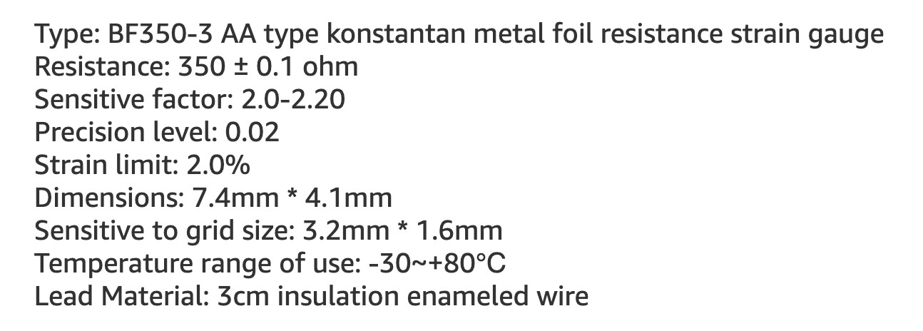
Post a sensor datasheet link.
I suspect that your bridge is so far out of balance that its "zero" is actually far greater than full scale when amplified by the HX711.
If your BF350 strain gauge is a 350 Ohm then you should be using high precision 350 Ohm resistors for the rest of your bridge. Otherwise you'll never get close to zero output with no load on the gauge. You could try balancing your bridge by putting a 10k potentiometer in parallel with your gauge resistor.
Hi thanks for the reply. All I've got are these 330 ohm resistors right now but I can try to get the 350 precision. In the meantime I've setup a potentiometer in parallel like you suggested and, with adjustment, I'm able to get values that are not that max value. Do you suggest that I adjust the potentiometer to get a reading of 0 or close to 0 for the raw output?
I am not I'm using 330 ohm resistors right from the a beginner arduino kit because that's all I have. I was looking for more of a proof-of-concept than super accurate measurements as of right now.
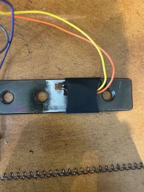
See attached the strain gauge setup. I've used regular super glue and soldered the wires on.
Unless you know what you are doing, if you are going to follow some video then you need to follow it exactly.
Use the same exact components, wiring and code.
The proper solution is to replace your 330 Ohm resistors with precision 350 Ohm resistors. That will get you close to a balanced bridge.
You can attempt to use the pot to zero the output but the resulting circuit will not produce a very linear output. I think the fact that it helped should tell you that your bridge needs resistors that are the same value as your gauge.
...the resistance isn't going to change more than 2.0*2.2=4.4% or 15Ω/350Ω at the strain limit so the 2nd order effects would be in the 0.2% range. Likely good enough for a proof a concept.
Nulling the balance with a pot would be the biggest fix.
By using a half bridge like in the video, you eliminate the error by having both legs of the bridge be the same resistance, 330 + 350, so the output is zero with no load. With your quarter bridge arrangement one leg is 330 + 330 and the other is 330 + 350 so you get an output of approximately 14.7mV per volt of excitation with no load on the bridge. It's even worse in practice because your 330 Ohm resistors are not exactly 330 Ohm. That multiplied by the gain of the amplifier in the HX711 gives you the large output voltage.
Actually, it might be just as linear--I think you get the same linearity with the pot adjusted to match the SG as you would if you used a matching SG--it is still the same ∆R of the SG in the same old voltage divider equation that induces the non-linearity. dig-dig...
... ... If the pot was in R3 and adjusted to 350 ohms, the linearity would the same, even if R1 &R2 were 330ohms or 1000ohms. If you instead put the pot in R1=350 with R3 &R4=330, you could still null out to Vo=0 but the nonlinearity of the voltage divider equation would be amplified a bit, since the gauge is a bigger fraction of the divider. So with a smaller fraction, like R3=R4=470ohm, it would be attenuated.
Still, using a pot (or a matched precision resistors) instead of a SG would lose the temperature compensation.