Hi there,
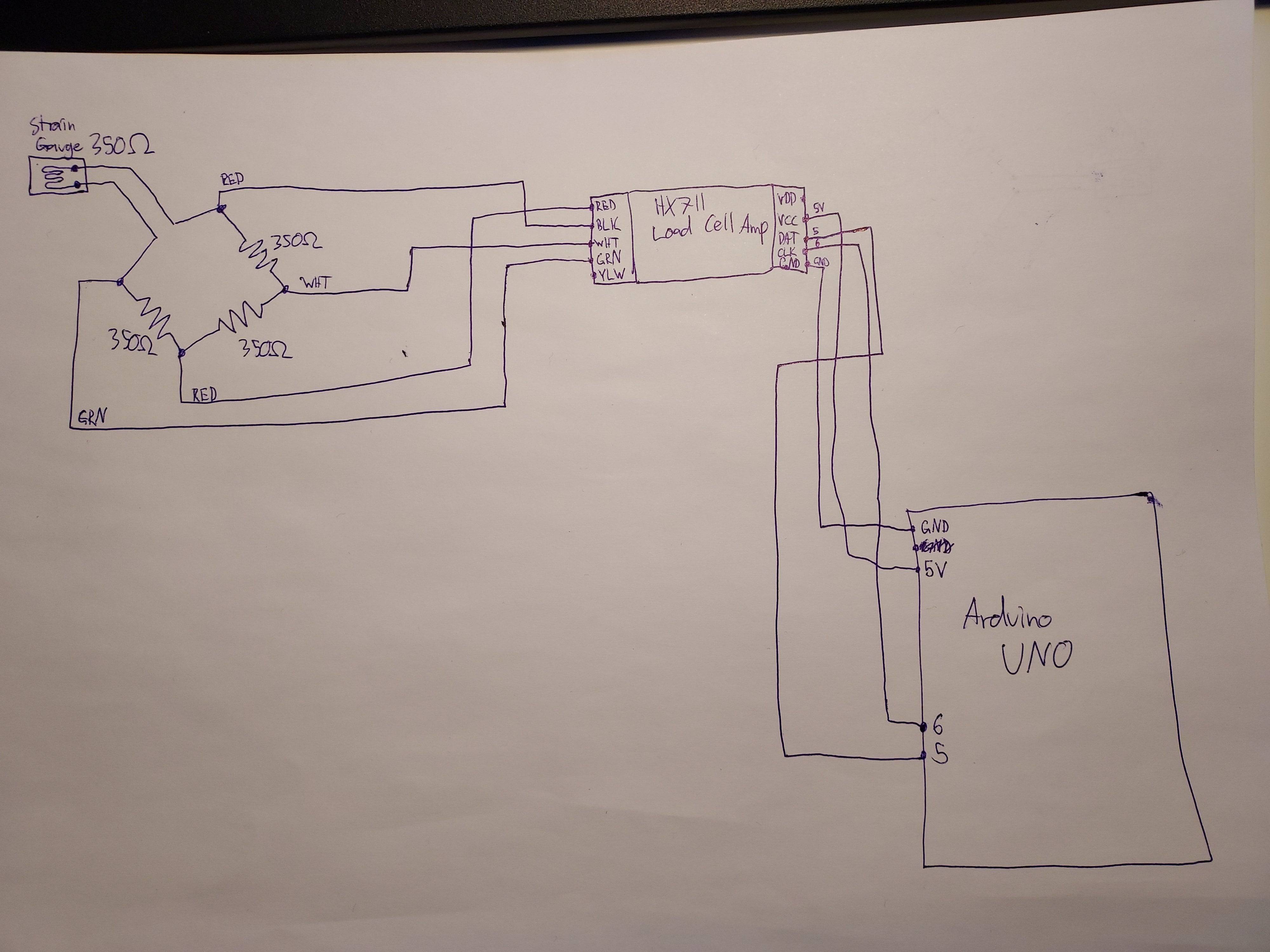
I am trying to get a strain gauge working with the HX711 load cell amp. I posted about this a few months ago and got told to get some high precision resistors for the wheatstone bridge. I have now obtained these (https://www.digikey.fi/product-detail/en/vishay-foil-resistors-division-of-vishay-precision-group/Y0007350R000T9L/Y0007-350-ND/2609877). My wiring and code are as shown below. I'm getting an entity too large error when I try to post the wiring image (even though it's under the size limit), but the wiring is basically a wheatstone bridge with one arm replaced by the straing gauge and each of the corners of the wheatstone bridge connected to RED, BLK, WHT and GRN on the red HX711 (BLK and GRN are the ones connected to the strain gauge arm). On the other side, VCC is to 5V on the arduino, GND to GND on the arduino, DAT to digital pin 5 and CLK to digital pin 6.
#include "HX711.h"


#define calibration_factor -550.0 //This value is obtained using the SparkFun_HX711_Calibration sketch


#define DOUT  5
#define CLK  6


HX711 scale;


void setup() {
  Serial.begin(9600);
  Serial.println("HX711 scale demo");


  scale.begin(DOUT, CLK);
  scale.set_scale(calibration_factor); //This value is obtained by using the SparkFun_HX711_Calibration sketch
  scale.tare(); //Assuming there is no weight on the scale at start up, reset the scale to 0


  Serial.println("Readings:");
}


void loop() {
  Serial.print("Reading: ");
  Serial.print(scale.get_units(), 1); //scale.get_units() returns a float
  Serial.print(" lbs"); //You can change this to kg but you'll need to refactor the calibration_factor
  Serial.println();
}
The problem is that the values are not changing when I bend the strain gauge. Only random, short, spikes in values are happening and they do not seem to correspond to the strain gauge being strained or unstrained. Any ideas what could be causing this?
Any help is greatly appreciated.