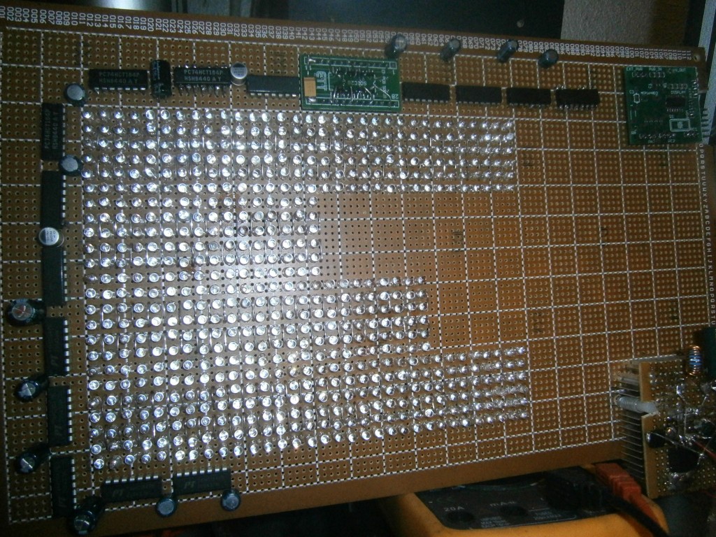
It is powered from 5 volts now, later I want to use a 12v electronic transformer
There is no cooling grid but a small fan under the voltage regulator.
I want to get some experience how much heat is produced and how much can be cooled away.
Right now connected a smaller matrix that I built some years ago, using standard LEDs (not high brightness). It works at 5 volts but also at 3.3 volts.
You can calculate how much current will be needed.
It will be based on how many LEDs can be on at one time.
That is based on how your are multiplexing.
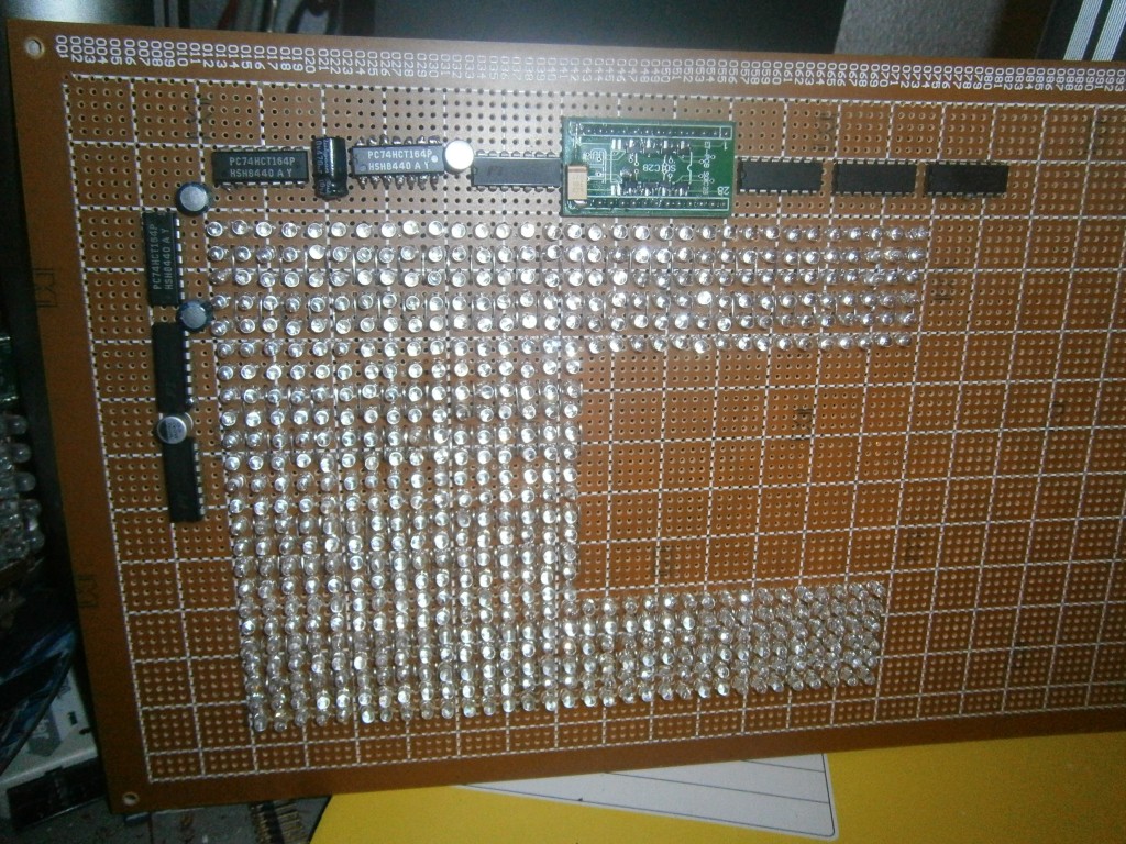
Your array seems to be 24 LEDs high and 32 LEDs across.
I would call that 24 Rows, and 32 columns.
I would also guess that you drive all 24 rows, and enable a column on & off.
Then drive the row data for the next column, and turn the column on & off.
Repeat for the remaining 30 columns.
That would mean you have 24 LEDs x 20mA/LED = 480mA.
No, I drive 32 Columns at once, but only activate one from 6 rows.
For 24 rows, 4 rows are active at any time.
I am not sure about 20mA limit.
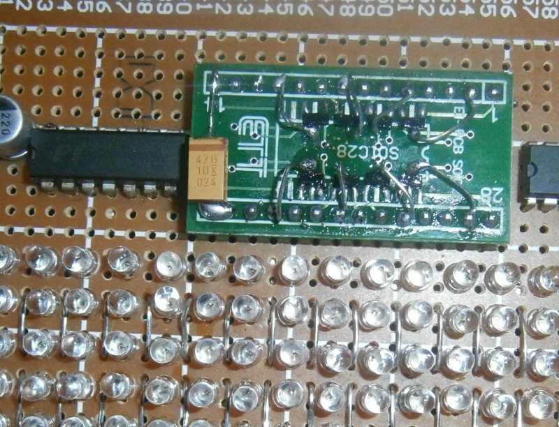
This is why I have the capacitors, and the 3.3v regulator.
The smaller matrix by the way, has 2 rows active at any time. It is a mess to program it in PIC RISC, even using 18F chip. I made the clock working but then just did not put more efforts into the project anymore.
Now I want to use 4 smaller controllers for the refresh/buffering, and 8 brightness levels.
And one bigger controller as the master, using the hardware serial port of the smaller devices to send them data. It is not easy because all 4 must be synchronized. Initially I will let them run unsynchronized to see how it looks like.
I am close to testing 1/4 of the matrix using only one controller.