Bike interface OBD

panmich
i haven't posted for a while, i have been super busy working on the Yamaha k-line.
Big Thanks to @TriB on this one!

His assisted immensely!

I have updated my main repo for the Yamaha Data logger.

It's mostly finished, I still need to tidy a few things up, If you have a look at my new code, it will explain how the data is handled

The short way is the YDS uses the same method as the AIM 5 byte stream protocol

The dash polls the ecu until the bike is running, then the 5 byte stream begins.

Any Yamaha Kline based dash should work fine, as they all share the 5 byte stream protocol.
However, if your bike has IMMO then it would be wise to choose a model with immo also, as the delay in the first dash poll will take into account the immoseq timing before the first poll is sent from the dash.

However, you could also try a xt125dash to see if the delay takes this into account.

Not sure what bike you have but the xt125 dash is cheap to buy, if you want something to get you out of trouble with your speed.

If you get stuck or need any info, drop me a pm.

Cheers

1 Like

thank you for your response . My bike is xt660x 2005 model. I will try to make a speedometer and to cheat the ecu so i will not have err-1 ( is the 0xfe code issued by the dash and the 0x01 later enough for this ? ). In normal running when we have the 5 byte sequence , how many milliseconds are from the 5 byte sequence to the next ? i saw in your posts that the speed calculation comes from the sum of last 8 sequences of the corresponding speed byte . Do you think that the value of each byte corresponds in some way to the pulses coming from the speed sensor ? if so we can make accurate calculations of the running distance (odometer).

panmich
HI, have you got Sigrok pulseview?
You don't need hardware to view logs, just grab the latest version, and you can view the logs attached in the zip file.

I have performed in depth Logic Analysis, for ECU Write, ECU Read, the Dealer YDT Tool ( the V1 Kline (Dash) does not support the tool), and the comms between the ECU/DASH. I have decoded the protocol and marked clearly marked in pulseview what is happening,

I used CLI to tidy up the data to convert it to useable format, which is also included. Along with simple scripts to perform various needed conversions and such.

This photo here, is all the possible ecu modes

  1. Normal mode
  2. CO
  3. Diag

I made a transparent bridge with 2 uarts. Which was able to pass successfully all data, (this would come in handy for the idea of separating the comms, allowing the code to boot into DIAG mode, Whilst retuning fake data to the DASH, to make sure the ER-1 does not occur dash side.

Whist being able to poll the menu in the ECU retrieving all information.

If you have a poke about on my rather messy github, you will find all of my Yamaha stuff. It does need a good tidy up for sure :slight_smile:

Back to your question you want, to save your time and others who may want to know this information
After IMMO/ECU happens, there is a 1280ms delay before the Dash polls the ECU

The First byte the Dash sends regardless of what mode is 0xFE, to which the ECU will always respond 0x00 0x00 0x00 0x01 0x01

Then further Dash Polls Normal mode will be 0x01
Diag will be 0xCD ( which is the user pressing both buttons on the dash)

Normal mode will be:
0x01 : RPM: VSS: ERROR: TEMP: CHECKSUM

Diag/CO mode will be
0xCD: 0x00 0x00 x00 0x01 0x01
For 7 seconds
then YDS menu will open, which in my other logs has been provided for each value

The nested menus are pretty easy to navigate, as you have already found out, the timing is critical to avoid ER1 ER2 ect

To note:
If 01 is polled, there is no further way of entering into the YDS mode, you have to reset the init

  • Although you can poll the "hidden" RPM Sub menu under C0, you cannot go elsewhere,

If you're in the YDS menu, and you press your starter button, The YDS will exit, and the ecu will resume normal boot mode.

YOUR CODE must listen for the IMMO poll! (54 byte sequence starting with (0x3e).) ** Use a flag** This immo poll happens 2 times, 1st time at startup, and the second time, when you press the starter button!

Failure to monitor for this will cause your IMMO poll to fail, if you talk to the ECU whilst the immo sequence is happening.

If you need anything further, or you want to know anything, or anybody else wishes to know anything, then please reach out to me, I started off learning this with 0 clue about MCUS, or Ardruino or circuits or code. I read this post a long time ago and did see that there was no updated info for the yamaha, soo my idea was simple, to decode the protocol and publish it to help others out like yourself.

With a lot of time, study and help from @TriB I managed to get to this stage.

If your on facebook, here is my post on the XT 660 forums, there is a full tutorial on how to flash the ECU, how to change and edit the maps, you should feel right at home if you want to cure the harsh low rpm buckeroo. , its not related to Arduino here, so i have not added the guide.

Also some photos for some of the things i managed to learn along the way :slight_smile:
My initial idea of using the USB KKL cable before i made my circuit ( mega + Relay for the IGN switch ) over RDP :slight_smile:

This was my early UART bridge, with sigrok

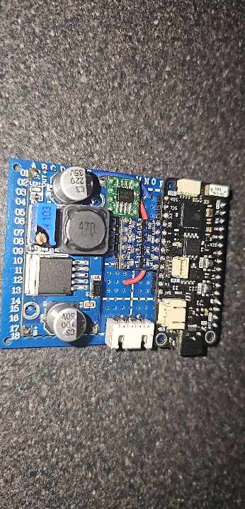
This was my v2 PCB ( Feather S3 )
Able to Fake the ECU to control the DASH

This is the TX, RX Pads on the Dash PCB,( they are the same lines used for the Kline bus) i was going to go this route, when i decide to upgrade the LDO on the pcb

finally this is my newest PCB, there is still room for the other L9637D, but I'm undecided how to progress further as of yet, I'm still finishing my code.

Cheers
Yamaha Protocol Analysis.zip (1.3 MB)

2 Likes

good evening sir would I have more data from the ECU emulator I am studying to develop a simulator for the Yamaha panel with Arduino, I intend to control rpm and speed via potentiometer for bench testing.

If you build a circuit that can interface with the dash 12v level shifting, this will be a good base for you to get started.

( it does not listen for a response) its just TX to the dash, (soo it does suffer bit drift)

But this will enable you to edit the code to use pots to adjust the values

Good morning,

I am currently working on my thesis project, which focuses on communication with the ECU of a 2024 Suzuki GSX-S150 motorcycle using an OBDII adapter cable. Our goal is to extract key information such as speed, RPM, fuel consumption, among others, through the diagnostic pins.

However, we have encountered an issue: we are unable to establish communication or retrieve any values. We suspect it may be related to the baud rate. According to the theory, to initiate communication, a hexadecimal code 33 is sent at 5 baud, and the ECU should respond with a hexadecimal 55 at 10400 baud. Despite following this procedure, we are not receiving any response.

We have also tried using an ELM327 adapter, but it returns an error, which I will attach along with the code we have been using for the project.

Any input or suggestions you can provide on how to proceed would be greatly appreciated.

Here is the code we are using:

#include <AltSoftSerial.h>

// Definir pines y constantes
AltSoftSerial KLine;  // Usaremos AltSoftSerial para la lectura de la respuesta
#define KLINE_PIN 9  // Pin para la K-Line

void setup() {
  // Inicializar la comunicación serie para depuración
  Serial.begin(9600);

  // Iniciar la comunicación serial en la K-Line
  KLine.begin(10400);  // Comenzar a 10400 baudios para leer la respuesta

  // Realizar secuencia de Wakeup
  Serial.println("Iniciando secuencia de Wakeup...");
  wakeupSequence();
}

void loop() {
  // Realizar Handshake a 5 baudios hasta que sea exitoso
  Serial.println("Iniciando handshake...");
  while (!handshakeSequence()) {
    Serial.println("Handshake fallido. Reintentando...");
    delay(1000);  // Esperar un momento antes de reintentar
  }

  Serial.println("Comunicación establecida.");
}

void wakeupSequence() {
  // Enviar el bit de wakeup manualmente
  pinMode(KLINE_PIN, OUTPUT);  // Control manual de la K-Line

  // Wakeup: Baja la K-Line a 0 por 200 ms, luego la sube a 12V (HIGH) por 20 ms
  digitalWrite(KLINE_PIN, LOW);
  delay(200);  // Baja a 0 por 200 ms
  digitalWrite(KLINE_PIN, HIGH);
  delay(20);   // Sube a HIGH por 20 ms

  Serial.println("Wakeup finalizado.");
}

bool handshakeSequence() {
  pinMode(KLINE_PIN, OUTPUT);
  Serial.println("Enviando byte 0x33 a 5 baudios...");

  // Secuencia de bits para 0x33 a 5 baudios:
  // Start bit (0) - 200 ms
  digitalWrite(KLINE_PIN, LOW);
  delay(200);

  // Bit 1 - 400 ms (dos bits 1 en 0x33)
  digitalWrite(KLINE_PIN, HIGH);
  delay(400);

  // Bit 0 - 400 ms (dos bits 0 en 0x33)
  digitalWrite(KLINE_PIN, LOW);
  delay(400);

  // Bit 1 - 400 ms (dos bits 1 en 0x33)
  digitalWrite(KLINE_PIN, HIGH);
  delay(400);

  // Bit 0 - 400 ms (dos bits 0 en 0x33)
  digitalWrite(KLINE_PIN, LOW);
  delay(400);

  // Bit de parada (1) - 200 ms
  digitalWrite(KLINE_PIN, HIGH);
  delay(200);

  // Cambiar el pin K-Line a entrada para recibir la respuesta
  pinMode(KLINE_PIN, INPUT);

  // Esperar y leer la respuesta del ECU
  delay(25);  // Pequeño retraso para permitir que la ECU responda
  if (KLine.available()) {
    uint8_t response = KLine.read();
    if (response == 0x55) {
      Serial.println("Respuesta de la ECU recibida: 0x55.");
      return true;  // Handshake exitoso
    } else {
      Serial.print("Respuesta inesperada de la ECU: ");
      Serial.println(response, HEX);
    }
  } else {
    Serial.println("No se recibió respuesta de la ECU.");
  }

  return false;  // Handshake fallido, se repetirá
}

And this is the error returned by the OBDII:

"Protocol check: 3) ISO 9141-2 (5 baud init, 10.4 kbaud) The ignition must be on or the engine must be started!"

The Bike is new enough to use OBD2 standard over CAN Bus, not K-Line.
So at least on Kawasaki, the K-Line is not in use anymore. It shows the ECU ID and that´s it.
Anything else works over CAN. So the GSX-S should have a red plug, which can be attached to any ELM327 with a simple adapter. And for your easy task to just show official documented values, any Car compatible ELM327 App can give you that information.

But that application theoretically tests all the protocols, but I can't connect to any of them,

Okay, first thing I´ve seen is that you use SoftwareSerial.
The standard Library does not support 10400 baud. It then takes the nearest value, which will be 9600 and does not work.
Where do you got the handshake sequence from? Using the K-Line and standard communication will require a startup message as hex, after your FastInit sequence.
How is you wiring? Do you use a L9637D?

But I´d first try to make an ELM327 work and ensure it´s doing what you need. Then start developing with the Arduino.
As I already asked, does the bike have the red six-pin diagnostic plug? Are you using an adapter or do you build it yourself?

I have a OBD Suzuki File from a 250R Suzuki around somewhere. I´ll take a look into it, when I found it.

Yes, we are using L9637D and you are right about the serial number.

What we did was test the OBDII on another Suzuki motorcycle and it works perfectly, we will now test it with the prototype, I hope it works.

Hey,
I found my files and saw that the Suzuki GSX250R from 2020 still works by K-Line.
But they were already using OBD2 commands.
No SID 0x21 for "Show current data" and PID0x08 to receive all at once. But SID 0x01 with the PID´s like you can see on the WiKi:
https://en.wikipedia.org/wiki/OBD-II_PIDs#Service_01

For such a new Bike like your´s I´m not sure if it will use still K-Line or CAN-Bus. But it at least should work with any ELM327 :man_shrugging:t2:

We are currently testing the ELMduino library to connect the ESP32 to the ELM327 via Bluetooth, and then request the PIDs. We are using a test code from GitHub with a car, but the ESP32 is unable to connect to the ELM327 via Bluetooth. I have tried everything, but nothing seems to work. Does anyone know what might be causing this issue? Here are the codes I am using.

/*
To test connection, type the following into the serial monitor:
  AT Z
  AT E0
  AT S0
  AT AL
  AT TP A0
*/

#include "BluetoothSerial.h"


BluetoothSerial SerialBT;


#define DEBUG_PORT Serial
#define ELM_PORT   SerialBT


void setup()
{
  pinMode(LED_BUILTIN, OUTPUT);
  digitalWrite(LED_BUILTIN, HIGH);

  DEBUG_PORT.begin(115200);
  ELM_PORT.begin("ESP32test", true);
  //ELM_PORT.setPin("1234");

  DEBUG_PORT.println("Attempting to connect to ELM327...");

  if (!ELM_PORT.connect("OBDII"))
  {
    DEBUG_PORT.println("Couldn't connect to OBD scanner");
    while(1);
  }

  DEBUG_PORT.println("Connected to ELM327");
  DEBUG_PORT.println("Ensure your serial monitor line ending is set to 'Carriage Return'");
  DEBUG_PORT.println("Type and send commands/queries to your ELM327 through the serial monitor");
  DEBUG_PORT.println();
}


void loop()
{
  if(DEBUG_PORT.available())
  {
    char c = DEBUG_PORT.read();

    DEBUG_PORT.write(c);
    ELM_PORT.write(c);
  }

  if(ELM_PORT.available())
  {
    char c = ELM_PORT.read();

    if(c == '>')
      DEBUG_PORT.println();

    DEBUG_PORT.write(c);
  }
}

and this

#include "BluetoothSerial.h"
#include "ELMduino.h"


BluetoothSerial SerialBT;
#define ELM_PORT   SerialBT
#define DEBUG_PORT Serial


ELM327 myELM327;


uint32_t rpm = 0;


void setup()
{
#if LED_BUILTIN
  pinMode(LED_BUILTIN, OUTPUT);
  digitalWrite(LED_BUILTIN, LOW);
#endif

  DEBUG_PORT.begin(115200);
  //SerialBT.setPin("1234");
  ELM_PORT.begin("ArduHUD", true);
  
  if (!ELM_PORT.connect("OBDII"))
  {
    DEBUG_PORT.println("Couldn't connect to OBD scanner - Phase 1");
    while(1);
  }

  if (!myELM327.begin(ELM_PORT, true, 2000))
  {
    Serial.println("Couldn't connect to OBD scanner - Phase 2");
    while (1);
  }

  Serial.println("Connected to ELM327");
}


void loop()
{
  float tempRPM = myELM327.rpm();

  if (myELM327.nb_rx_state == ELM_SUCCESS)
  {
    rpm = (uint32_t)tempRPM;
    Serial.print("RPM: "); Serial.println(rpm);
  }
  else if (myELM327.nb_rx_state != ELM_GETTING_MSG)
    myELM327.printError();
}```

Hello, I am using your Yamaha Kline sniffer, for my Tmax 500, but I display 2 lines, 01 and 02 and I have a problem on the speed, the wheel sensor sends a pulse every 120 degrees. And he sends them randomly on the two lines (same column as the speed). So I have three 1's every spin of the wheel, and I thought that was enough. but I noticed that increasing the speed (after about 70 km/h) the columns are full of 1 but then a 2 begins to appear. In fact, imagining a 1 at each pulse I calculated the speed but strangely at 66km/h the speed display froze. Then I discovered that after that speed, a 2 also appears. Can you help me understand how this ECU of the Yamaha Tmax 500 from 2006 works?

hi TriB I've written to you before, I've also shared the start codes for the 2006 honda varadero. do you have a code and schematic diagram that works for my honda?

Hi,
I still have no Honda available, yet.
So I don´t have more to share then the links and Raspberry PI solutions, I already submitted.

But from Hardware perspective, when the Honda still used K-Line to communicate, then it is the same schematic as for Suzuki and Kawasaki.

Hi all!
I'm trying to connect my kawasaki using @TriB OBD-II bluetooth project OBD II Bike Connector - Pass via bluetooth - #248 using Car Scanner app.
Could you tell me the proper init protocol to connect app to the bike?
I tried 10.4kbps fast init and 5 baud init but it doesn't work either.
Here you can see the time sequence in arduino uart lines:


Ch1: arduino TX to L9637 kline transceiver
Ch2 & Ch3: arduino to bluetooth module uart.

It seems the init sequence starts with the corresponding 25ms step down but after that, nothing happens (but a re-attempt 3.8secs after).

Any suggestion?

Hello TriB, I re-read the form from where I left off. I think no one can get data on the Honda motorcycle or I missed it. If I missed it, can you help me? At least about a sample starting code. I ordered l9637d. This is a starting code in the serial screen related to the connection diagram between the integrated and the arduino. Thank you in advance.

Hi eraydagci,
no it is possible to read data from a Honda ECU.
And all the calculations are documented by Gonzo (you already found the link) and just need to be adapted from his RaspberryPi Solution to Arduino.
I cannot to this myself, due to missing Honda and two little children, which have a higher priority right now :wink:

Searching for something similar, leaded me to this:

Seems like a great startingpoint for you!

hello community if you want to have fun I put on my repository a set of files for the motorcycle

2 Likes

Hello everyone.

I would first like to give a thank you to TriB and everyone else that have given input to this topic. I am trying to implement this solution and I will try to be brief on my explanation.

My setup is an Arduino Nano, HC06 and L9637D and resistors/capacitors to go along with them. The hardware works and I have managed to get a connection to my ECU.

However, I have found great difficulty in getting the software to work. I am not an SW engineer and I do nut fully understand how the code works. That being said, I have pinpointed my issues to this.

The OBD app sends request as 01 XX, for example 01 0C. I am able to respond to these requests with the emulator. Suzuki wants it to be 21 0C and I found that there is code for translation in the repo (HerrRiebmann/KDS2Bluetooth). If I interpreted the code correctly that translation is not called in the code anywhere and I am looking for a way to implement that.

My end goal is to have a device that can send live data to a device (camera or phone) and read and clear DTC. Here is what I have in the Arduino currently:

//Suzuki specific fork
#define NewBoard 0
const float FWVersion = 1.17;
#if NewBoard
const float BoardVersion = 1.30;
#else
const float BoardVersion = 1.00;
#endif

//FW 1.01: Logger optimization & Gear-Test
//FW 1.02: Advance & Gear transmission
//FW 1.03: Cleanup (Size)
//FW 1.04: Function for testing
//FW 1.05: Code Cleanup
//FW 1.06: Gearratio above 20kmh & 2000rpm
//FW 1.07: Long BT-Commands didn´t work (Timeout), Lowercase on BT, Error printout chars
//FW 1.08: Added functionality to fetch data from a working communication
//FW 1.09: Kawasaki ABS
//FW 1.10: Bluetooth initialization (for HC-06-20190901)
//FW 1.11: K-Line Buffer exceeded (wrong check) & sized to 133, don´t print via BT when debugMode active, code cleanup, Transmission Current Gear & Enginge Runtime, Reduced Timings
//FW 1.12: Kawa DTC, Yamaha, FetchMode enhancement
//FW 1.13: Suzuki Factor to 256, optimized test-function (XTXi)
//FW 1.14: Read all freezed frames (Kawa only)
//FW 1.15: ELM327:1.4 -> 1.5 (For SZ Viewer A1 compatibility)
//FW 1.16: Revert back to ELM327:1.4, Added ATKW & ATCAF (Several CAN-Bus configs), Optimized FetchData()
//FW 1.17: Sniffer/Fetch-mode optimizations 

//_**  Libraries   **_//
#include <EEPROM.h>
#include <SoftwareSerial.h>

//_**  EEPROM Storage   **_//
#define EEPROM_Offset 1
#define EEPROM_Error_Counter 2

#define EEPROM_BTVersion 10
#define EEPROM_BikeProtocol 11
#define EEPROM_RawMode 12
#define EEPROM_TemporaryStorage 13
#define EEPROM_AutoGear 14

#define EEPROM_ThrottleMin 20
#define EEPROM_ThrottleMaxLow 21
#define EEPROM_ThrottleMaxHigh 22
#define EEPROM_SubThrottleMin 25
#define EEPROM_SubThrottleMax 26

#define EEPROM_Error_ID 40
#define EEPROM_Error_SID 41
#define EEPROM_Error_PID 42
#define EEPROM_Error_7F 43
#define EEPROM_Error_Min 44  //Minutes since start

//_**  Error Types  **_//
#define ERROR_StartCom 1
#define ERROR_Checksum 2
#define ERROR_Receive_Timeout 3
#define ERROR_7F_Response 4
#define ERROR_Unknown_SID 5
#define ERROR_Unknown_PID 6
#define ERROR_BT_Timeout 7
#define ERROR_Unkonwn_InitProtocol 8
#define ERROR_7F_Response_KA 9
#define ERROR_FastInit 10
#define ERROR_SlowInit 11
#define ERROR_StopCom 12
#define ERROR_BT_VersionNotFound 13
#define ERROR_BT_BaudNotFound 14
#define ERROR_BT_BaudNotChanged 15
#define ERROR_BT_WrongVersionInEeprom 16
#define ERROR_ELMnoData 20
#define ERROR_Unknown_AT 21
#define ERROR_Unknown_XT 22
#define ERROR_Unknown_CMD 23
#define ERROR_BT_Buffer_Exeeded 24
#define ERROR_K_Buffer_Exeeded 25

//_**  Bluetooth Interface   **_//
#define BT_Timeout 500  // 0,5 second timeout on Wireless commands
#define BT_Delay 3      // 3 ms delay between reads if nothing available
#define BT_Baud 9600
#define BT_BaudFallback 9600
#define BT_Cmd_Delay 2000 //Previously 1000, but since new BT module 2sec

#define BUFFER_SIZE 133         //Suzuki PID 0x80 length 102 + header & checksum (should be max 128 for data + 5 for header & checksum)
uint8_t btBuffer[BUFFER_SIZE];  //Incoming hex from Bluetooth
uint8_t btBufferCounter = 0;
uint8_t btIncomingCounter = 0;
uint8_t hexBuffer = 0xFF;
long baud = 0;

SoftwareSerial BT(10, 11);

uint32_t lastBtRequest;
bool IsHexRequest = false;
uint8_t btVersion = 0xFF;

//_**     K-Line    ## //
#define K_IN 0                   // K Input  Line - RX (0) on Arduino
#define K_OUT 1                  // K Output Line - TX (1) on Arduino
#define K_MaxSendTime 2000       // 2 second timeout on KDS commands
#define K_ErrorTimeout 1000      // 500 minimum //-> Max value 5 seconds timeout before reinitialization. (Minimum 55?)
#define K_Baud 10400             // Should be 10417
#define K_Keepalive 1500         // 1,5 seconds no request, send keepalive (2s is ECU timeout)
#define K_ISORequestDelay 55     // 55 MS between requests. (25 MS between two requests, 55 MS after response)
#define K_ISORequestByteDelay 5  // 5 MS between single bytes.

bool ecuConnected = false;
uint32_t lastKlineResponse = 0;
uint8_t customFormat = 0xFF;
uint8_t ecuAddress = 0x12;  // 0x11 & 0x28 Kawasaki (ECU & ABS), 0x12 Suzuki, 0x33 Yamaha
uint8_t myAddress = 0xF1;
uint8_t bikeProtocol = 4;  // Kawa, KawaABS, Suzuki1, Suzuki2, Honda1, Honda2, (MV Augusta Brutale - Should be possible), Yamaha
uint8_t keepaliveMsg[3] = { 0x3E, 0xFF, 0xFF };

uint8_t ecuBufferIn[BUFFER_SIZE];  //Incoming hex from ECU
uint8_t ecuBufferInCounter = 0;
uint8_t ecuBufferOutTmp[5] = { 0xFF, 0xFF, 0xFF, 0xFF, 0xFF };  //Temporary outgoing hex to ECU for individual messages
uint8_t ecuBufferOutTmpCounter = 0;

//_**   Throttle Percentages   **_//
uint8_t throttlePosMinimum = 39;   //Kawa 201, Suzi 39
uint16_t throttlePosMaximum = 221;  //Kawa 892, Suzi 221
uint8_t subThrottleMinimum = 26;    //Kawa 81,  Suzi 26
uint8_t subThrottleMaximum = 185;   //Kawa 189, Suzi 185

//_**   ELM Setup   **_//
bool header = false;
bool spaces = false;
bool linefeed = false;
bool echo = false;
bool memory = false;
uint8_t adaptiveTiming = 0;
uint8_t isoProtocol = 5;  //5: ISO 14230-4 KWP (fast init, 10.4 kbaud)
const char elmVersion[] = "ELM327 v1.4";

//_**   Custom Setup   **_//
bool sendKeepAlive = false;
bool debugMode = false;
bool fetchMode = true; // Always on for live data polling
bool tempStorage = true;
bool autoGear = false;
bool rawMode = false;
bool bypassInit = false;
bool defaultCheckSum = true;
uint16_t Factor = 255;
uint8_t eepromOffset = 0;
uint8_t errorCounter = 0;
uint32_t lastDataUpdate = 0;

#define LED_STATUS A0  //Board V2

void setup() {
  InitializeStatusLed();
  SetStatusLed(HIGH);

  InitializeKLine();

  InitializeStorage();
  
  InitializeBluetooth();

  InitializeManufacturer();
  SetManufacturerProtocol();

  SetStatusLed(LOW);
}

void loop() {
  ReadAvailableInput();

  //PrintErrorMessages();
  // check bluetooth timeout:
  CheckInputTimeout();

  // send keepalive message
  if (CheckIdle())
    StayAlive();
}

void InitializeStatusLed() {
  pinMode(LED_STATUS, OUTPUT);
}

void SetStatusLed(const bool state) {
  digitalWrite(LED_STATUS, !state);
}

Please advise.