Problem: Motor runs in only one direction. Depending on the wires plugged in (which I understand why). But my bipolar motor won't run when all 4 wires are plugged in. When 3 wires are plugged in it rotates based on the code shown below. It only rotates on option 0 though.
#include <Stepper.h>

// change this to fit the number of steps per revolution

const int stepsPerRevolution = 48;

Stepper myStepper(stepsPerRevolution, 8, 9, 10, 11);

int stepCount = 0; // number of steps the motor has taken

char data;

void setup() {

Serial.begin(9600);

myStepper.setSpeed(60);

displayInstructions();

}

/**

Displays instructions to user

*/

void displayInstructions() {

Serial.println("READY - PLEASE SEND INSTRUCTIONS AS FOLLOWING :");
Serial.println("\t0 : Send clockwise");

Serial.println("\t1 : Send counter-clockwise");

Serial.println("\t2 : Stop turning\n");

}

void loop() {

if (Serial.available()) {

data =` [`Serial.read`](https://Serial.read)`();

switch (data) {

// 0

case 48:

Serial.println("Running CW");

myStepper.step(stepsPerRevolution);

delay(500);

//runStepper(1);

break;

// 1

case 49:

Serial.println("Running CCW");

myStepper.step(-stepsPerRevolution);

delay(500);

//runStepper(-1);

break;

// 2

case 50:

Serial.print("Stopping");

Stop();

break;

}

}

}

void runStepper(int dirStep) {

Serial.println(dirStep);

while (stepCount < 500) {
Serial.print("steps:");

Serial.println(stepCount);

myStepper.step(dirStep);

stepCount++;
}

Stop();

}

void Stop() {

stepCount = 0;

Serial.print("Stopped");

myStepper.step(0);

}
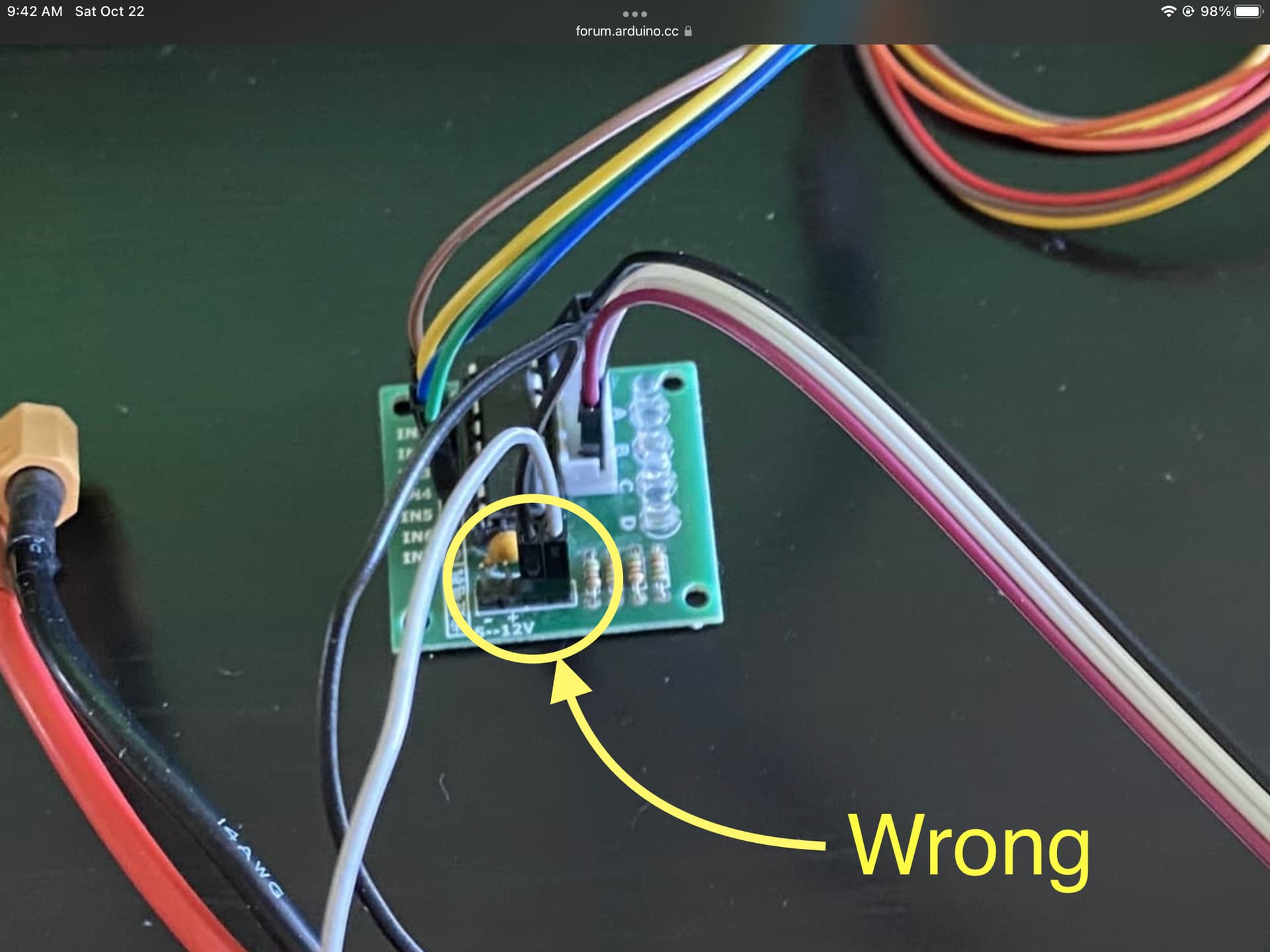
Below is how everything is wired... I hope you can follow the image and the wires.
Wiring with all 4 wires plugged in. from left (Brown) to right(blue). B1-A => 8, B1-B =>9, GND => GND, power => power, A1-A => 10, A1-B => 11:
IMPORTANT: In the next photo I only remove the brown wire. Which is B1-A => 8. So only three wires are plugged in from ports 9-11. And it works in only one direction.
Excess info: The code basically rotates the stepper motor 1 whole revolution. And again. It works only when three wires are plugged in. But I want it to work when 4 wires are plugged in. Not sure why it isn't working when 4 wires are plugged. It won't rotate in the opposite direction when 3 wires are plugged in. It only rotates in one direction and only responds to an input of 0 in the serial monitor.
the black power is connected to power and the orange one to ground. I know, the colors don't match. i know the color standards aren't usual convention.
Your pictures are very confusing. In your first post, you wrote about a L9110 motor controller:
But on the pictures I see a ULN2003 board. And even more confusing, the ouputs of this board are connected to the UNO, and the inputs are connected to the stepper???
But anyway. You can't control your stepper with a ULN2003, you need an H-bridge like the L9110.