Hi,
A Waveshare e-paper B&W 5.79inch connected to a Nano 33 IoT appears to be running setup() but with timeout issues based on the Serial Monitor output. The e-paper display shows no sign of life. Any recommendation on how to proceed debugging?
I'm using the GxEPD2 library ver 1.6.1 and a provided example GxEPD2_Example.ino. Arduino IDE ver 2.3.4.
Here's a snippet of the the start of the Serial Monitor output:
Entered setup()
pages = 2 page height = 151
Busy Timeout!
_Update_Full : 10000680
Busy Timeout!
_Update_Full : 10000781
Busy Timeout!
_Update_Part : 10000884
Busy Timeout!
_Update_Part : 10000939
Busy Timeout!
...
2 pages looks correct, but not sure that 151 for height is correct. Display is supposedly 792x272 pixels. I added 'Entered setup()'.
Nano compile stats:
Sketch uses 85660 bytes (32%) of program storage space. Maximum is 262144 bytes.
Global variables use 19288 bytes (58%) of dynamic memory, leaving 13480 bytes for local variables. Maximum is 32768 bytes.
In GxEPD2_display_selection_new_style.h, here's the 5.79in related classes uncommented:
// select the display class (only one), matching the kind of display panel
#define GxEPD2_DISPLAY_CLASS GxEPD2_BW
and
#define GxEPD2_DRIVER_CLASS GxEPD2_579_GDEY0579T93 // GDEY0579T93 792x272, SSD1683 (FPC-E004 22.04.13)
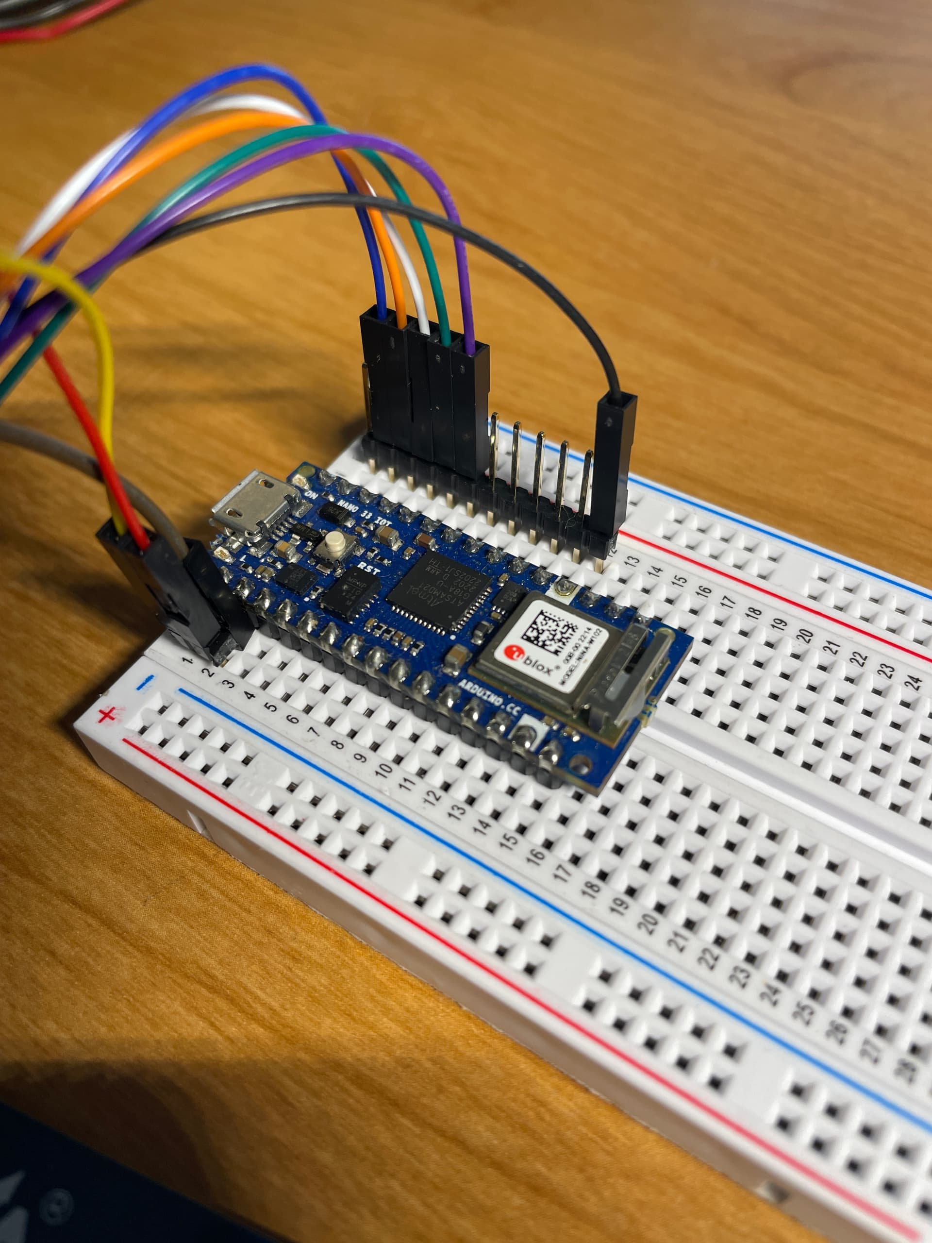
Here is the display <> Nano mapping: (triple-checked)
VCC (red) <> +3V3
GND (blk) <> GND (next to D2)
DIN (blu) <> D11
CLK (ye) <> D13
CS (or) <> D10
DC (grn) <> D8
RST (wh) <> D9
BUSY (purple) <> D7
PWR (brn) <> +3V3
On the back of the display board there is a jumper soldered to the 0 side which looks to indicated 4-wire SPI.