This is not my first Arduino project, but it's been a few years (mechatronics education). I'm going to attempt to implement a circuit design to remotely control the speed of a Nema 34 stepper. I'm asking if someone with experience using the HC-05 modules can take a look at the wiring diagram before I get started on coding and let me know if there are any obvious issues/mistakes in this circuit. I do not have parts yet (on order...mid next week).
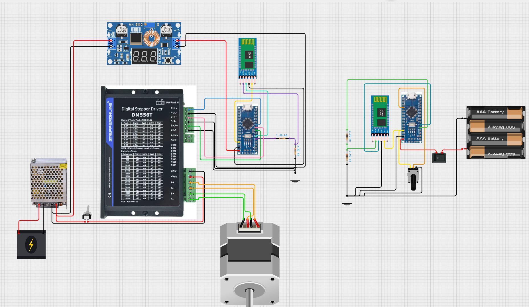

Please make schematics for at least the HC-05 section. Those pictures are not useful for telling. Pin names are interesting but pin positions tell nothing as most helpers don't know all Your circuitry by heart.

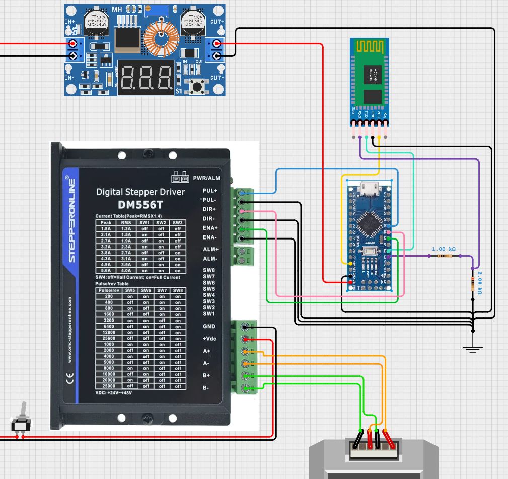
I agree the screenshots were not ideal for a wiring diagram. Here is a schematic that may be more useful... for telling.
You have connected 5 volt to Vin. I'm not sure that's good. Check the datasheet for the voltage range.
Also checck the HC-05 datasheet for the current needed. Taking the 5 volt from the Arduino might be good, might be not good.
Applying 220 volt AC to the stepper driver looks like popping it to me.
1 Like
It is not good. If you have a regulated +5V supply, you can feed that directly into the +5V pin on the Nano. The Vin pin goes to the on board voltage regulator so it needs 6-12V.
1 Like
Depends on the StepperOnLine driver he is planning to use.
@tjpayne has shown a DM556T with DC input voltage only, and a DM860 which can accept AC voltage input.
Okey but how much of voltage? The datasheet surely tells.
From datasheet:
Input voltage 18-80VAC or 36-110VDC
220V AC is definitely too much.
1 Like
I had to look up that spec sheet for a Nano. Thank you--Vin takes 6 to 12V. The Nano has a max current draw of 50mA (I'm assuming that's 3.3V, probably 30-40mA for 5V?). The HC-05 has a Vcc input range of 3.3-6V with a working draw of 30mA.
I think I will still pull power into the Nano from a 5V supply, but to the 5V pin. Then I'll power the HC-05 Vcc via 3.3V from the Nano. This should sort out the power issues you pointed out, thoughts?
Nice catch! In the original diagram (from Cirkit) I did use a DM556 driver and hooked it to a 24V supply. In the schematic from EasyEDA I changed to a 220Vac source and the DMA860. I was still trying to determine what I wanted the stepper/driver setup to look like...apologies for the confusion.
Consequently, I will edit the schematic to properly reflect what I Actually decided to do--use a DM2282T from stepperonline which takes a 180-240Vac input. This is so that I could potentially run a Nema34 or 42 stepper with the 8.2A peak current output.
But be aware, that you should not connect it directly to your mains outlet - even if the voltage fits. You need to use a transformer for safety reasons. See datasheet:


1 Like
Thanks for that reminder! I remember that isolation transformers are generally good practice for AC supply to electronics. Because I'm using mains power, I will search for a 1:1 isolation transformer to add to the circuit.
This topic was automatically closed 180 days after the last reply. New replies are no longer allowed.