Hi All,
I have a problem managing the absolute angles on a BMI160 IMU sensor , the sensor is connected in i2C to an Atmega2560.
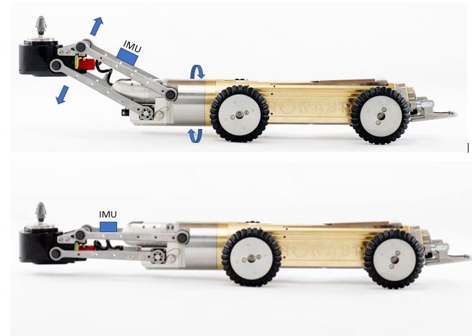
Phisically the board is mounted on an arm that can rotate 360° around IMU X axis and tilt around Y axeis +/- 80°.
The problem I have is that "Roll" angle ( arm rotation) start from 0 and go to +/-90° depending on rotation side and then start decreasing again to 0 , for example a real 100° return 80°, at the same time Pitch angle jump from 0 to something close to 180° when roll pass 90°.
I tried this code that use different type of filters but all the outputs have the same behaviour exept the gyro_roll that measure a full 360 angle but is obviously subject to a big drift overtime.
Someone that face the same problem can help me ?
Thanks in advanced
Flavio
#include <Wire.h>
#include <math.h>
#include <BMI160Gen.h>
#include <Kalman.h>
#include <MadgwickAHRS.h>

#define PRINT_PROCESSING

#define BAUDRATE  115200
#define SENSE_RATE   100
#define GYRO_RANGE   250
#define ACCL_RANGE     2

#define deg_to_rad(a) (a/180*M_PI)
#define rad_to_deg(a) (a/M_PI*180)

Kalman kalmanRoll;
Kalman kalmanPitch;
Madgwick madgwick;

float convertRawGyro(int gRaw) {
 // ex) if the range is +/-500 deg/s: +/-32768/500 = +/-65.536 LSB/(deg/s)
 float lsb_omega = float(0x7FFF) / GYRO_RANGE;
 return gRaw / lsb_omega;  // deg/sec
}

float convertRawAccel(int aRaw) {
 // ex) if the range is +/-2g ; +/-32768/2 = +/-16384 LSB/g
 float lsb_g = float(0x7FFF) / ACCL_RANGE;
 return aRaw / lsb_g;
}

static float gyro_roll = 0, gyro_pitch = 0, gyro_yaw = 0;
static float comp_roll = 0, comp_pitch = 0;
static unsigned long last_mills = 0;
void print_roll_pitch()
{

 // read raw accl measurements from device
 int rawXAcc, rawYAcc, rawZAcc; // x, y, z
 BMI160.readAccelerometer(rawXAcc, rawYAcc, rawZAcc);
 float accX = convertRawAccel(rawXAcc);
 float accY = convertRawAccel(rawYAcc);
 float accZ = convertRawAccel(rawZAcc);

 float rad_a_roll = atan2(accY, accZ);
 float rad_a_pitch = atan2(-accX, sqrt(accY*accY + accZ*accZ));
 float accl_roll = rad_to_deg(rad_a_roll);
 float accl_pitch = rad_to_deg(rad_a_pitch);

 // read raw gyro measurements from device
 int rawRoll, rawPitch, rawYaw; // roll, pitch, yaw
 BMI160.readGyro(rawRoll, rawPitch, rawYaw);
 float omega_roll  = convertRawGyro(rawRoll);
 float omega_pitch = convertRawGyro(rawPitch);
 float omega_yaw   = convertRawGyro(rawYaw);

 unsigned long cur_mills = micros();
 unsigned long duration = cur_mills - last_mills;
 last_mills = cur_mills;
 double dt = duration / 1000000.0; // us->s
 if (dt > 0.1) return;

 // Gyro data
 gyro_roll  += omega_roll  * dt; // (ms->s) omega x time = degree
 gyro_pitch += omega_pitch * dt;
 gyro_yaw   += omega_yaw   * dt;

 // Complementary filter data
 comp_roll  = 0.93 * (comp_roll  + omega_roll  * dt) + 0.07 * accl_roll;
 comp_pitch = 0.93 * (comp_pitch + omega_pitch * dt) + 0.07 * accl_pitch;

 // Kalman filter data
 float kalm_roll  = kalmanRoll.getAngle(accl_roll, omega_roll, dt);
 float kalm_pitch = kalmanPitch.getAngle(accl_pitch, omega_pitch, dt);

 // Madgwick filter data
 madgwick.updateIMU2(omega_roll, omega_pitch, omega_yaw, accX, accY, accZ, dt);
 // madgwick.updateIMU(omega_roll, omega_pitch, omega_yaw, accX, accY, accZ);
 float madw_roll  = madgwick.getRoll();
 float madw_pitch = madgwick.getPitch();
 float madw_yaw   = madgwick.getYaw();

#ifdef PRINT_PROCESSING
 static int n = 0;
 if (n != 50) {
   ++n; return;
 }
 n = 0;

 Serial.print(accl_roll);
 Serial.print(",");
 Serial.print(accl_pitch);
 Serial.print(",");
 Serial.print(madw_yaw);
 Serial.print(",");
 Serial.print(gyro_roll);
 Serial.print(",");
 Serial.print(gyro_pitch);
 Serial.print(",");
 Serial.print(madw_yaw);
 Serial.print(",");
 Serial.print(comp_roll);
 Serial.print(",");
 Serial.print(comp_pitch);
 Serial.print(",");
 Serial.print(madw_yaw);
 Serial.print(",");
 Serial.print(kalm_roll);
 Serial.print(",");
 Serial.print(kalm_pitch);
 Serial.print(",");
 Serial.print(madw_yaw);
 Serial.print(",");
 Serial.print(madw_roll);
 Serial.print(",");
 Serial.print(madw_pitch);
 Serial.print(",");
 Serial.print(madw_yaw);
 Serial.print(",");
#endif
 Serial.println();
}


void setup() {
 Serial.begin(115200);
 BMI160.begin(BMI160GenClass::I2C_MODE);
 madgwick.begin(SENSE_RATE);

 BMI160.setGyroRate(SENSE_RATE);
 BMI160.setAccelerometerRate(SENSE_RATE);
 BMI160.setGyroRange(GYRO_RANGE);
 BMI160.setAccelerometerRange(ACCL_RANGE);

 BMI160.autoCalibrateGyroOffset();
 BMI160.autoCalibrateAccelerometerOffset(X_AXIS, 0);
 BMI160.autoCalibrateAccelerometerOffset(Y_AXIS, 0);
 BMI160.autoCalibrateAccelerometerOffset(Z_AXIS, 1);

 delay(100);

 /* Set kalman and gyro starting angle */
 int rawXAcc, rawYAcc, rawZAcc;
 BMI160.readAccelerometer(rawXAcc, rawYAcc, rawZAcc);
 float accX = convertRawAccel(rawXAcc);
 float accY = convertRawAccel(rawYAcc);
 float accZ = convertRawAccel(rawZAcc);

 float roll  = rad_to_deg(atan(accY / accZ));
 float pitch = rad_to_deg(atan(-accX / sqrt(accY * accY + accZ * accZ)));

 // Set starting angle
 kalmanRoll.setAngle(roll);
 kalmanPitch.setAngle(pitch);
 gyro_roll  = comp_roll  = roll;
 gyro_pitch = gyro_pitch = pitch;
}

void loop() {
 print_roll_pitch();
}