When designing a device in which I planned to use BMI160 for orientation, I ran into the problem of axis orientation.

Using an example sketch from https://docs.arduino.cc/library-examples/curie-imu/Genuino101CurieIMUOrientationVisualiser
By default, the orientation of the sensor is

The x-axis is directed to the north, the y-axis to the west, and the z-axis to the sky.
When the board is level, I get great roll, pitch, and yaw angles.
But I need to use the board with the sensor in a vertical position like this

But as soon as I turn the board on edge, the zed axis is immediately limited in movement and I get a gimbal lock.
The other axes are also nonsense, not data.
I began to look for information on how to reassign the axes, but I did not find anything - only a licensed solution from Bosch itself in the form of software.
I tried to calibrate offsets, but nothing changes after calibration - as if the axes are not calibrated at all.
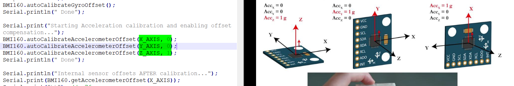
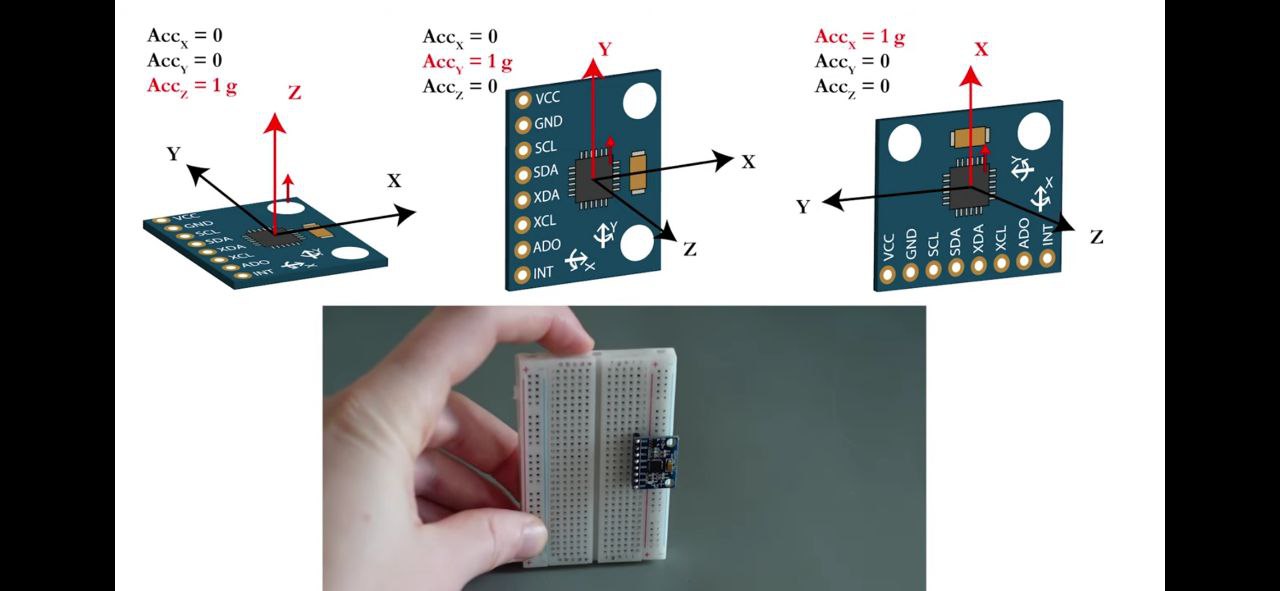
I determined that when the board is parallel to the table, then the acceleration along the zed axis is about 1, along the other axes zero
When I turn the board on edge, the x-axis becomes one, the other axes are zeros.
I edited the offsets, but nothing has changed.
a: -0.19 0.06 0.97
    BMI160.autoCalibrateGyroOffset();

    BMI160.autoCalibrateAccelerometerOffset(X_AXIS, 1);
    BMI160.autoCalibrateAccelerometerOffset(Y_AXIS, 0);
    BMI160.autoCalibrateAccelerometerOffset(Z_AXIS, 0);
I can’t understand anything, the datasheet says that you can use the sensor in any orientation, but I can only receive normal data in the horizontal space of the board.
My code takes the raw data from the accelerometer and gyroscope, converts it into gee values for the accelerators and into angular velocities for the gyroscopes.
Then I filter the data through the Madgwick filter, the output of which is a normalized quaternion.
And after the quaternion I convert it to roll, pitch and heading angles.
Is it possible for me to reorient the axes - do I need to change the values in the quaternion?
It turns out that with the rotation of the board from the sensors from the horizontal to the vertical plane, the z-axis became the x-axis, and the x-axis became the z-axis.
The Y-axis is left as is.
Moreover, an example for processing, using transformation matrices - somehow gets a normal orientation at the output ...

I tried to substitute the swapped axes in the filter, but the output was not what I needed.
I used to think that working with accel and gyro sensors was not very difficult.
Connected via the I2C bus, requested the value Ax,Ay,Az, Gx, Gy,Gz and filter whatever you want.
I thought you can arrange the board as you like, at the right time including calibration and zeroing the readings in order to count from the desired position.
And in fact, nothing works.
In general, I can’t understand how I get a quaternion - as a result, I encounter a gimbal lock?
Also I don't understand why I need rotation/transformation matrices to display roll/pitch/heading?
Confusion and porridge in my head ...