Hi, wonder if someone can help me, if i have a battery pack with several cells in series, so i have 0v, then 4v then 8v then 12v etc etc,
whats the bets way to get each of the voltages in to an arduino? of course if it was just 1 i could use an anolog input, it would have apx 21 cell packs so up to a total of max 100v,
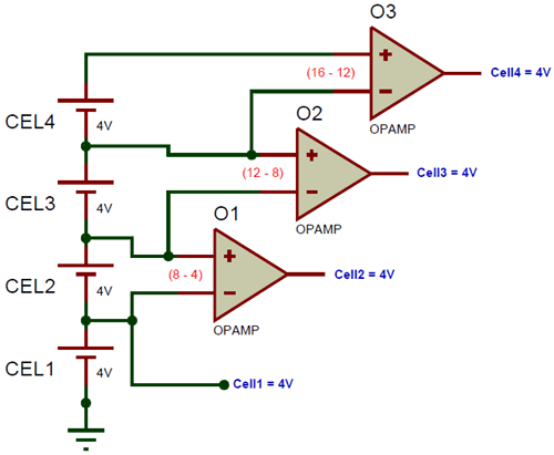
If I'm understanding correctly, you want to measure the voltage at each positive terminal? You should show a diagram of exactly what you're trying to do.
Yes exactly that, so as the cells discharge it will read lots of decreasing voltages, each voltage difference will be smaller than 5v but of course other than the first one each will be higher than 5v incomparison to the ground,
That's not a basic diagram, that's a complete IC. If you try to copy that and don't know exactly what you're doing, you're probably going to start a fire and/or fry your board. Before undergoing such a project, is it really necessary to know individual voltages and not leave it to a board dedicated to the process?
it was only the cell/monitoring points i was pointing out,
Im only trying to get the voltage levels in to the arduino nothing else, if it detects a low cell pack i can then turn the controller to a lower power level,
You could use a multiplexer (like this one) to read 16 analog signals over a single line. You could cycle the multiplexer through each channel and read each of your cells individually, one by one. It would be best to access both terminals of each of the 21 cells and read them independently so that the voltage is always 4V for each cell, instead of reading them all with reference to ground. You would not have to deal with increasing and higher voltages in this way.