Brass annealing that almost broke my brain and patience

I thought I'd share this project I've been working on. Comparatively, I'm in my programming infancy and in actuality this was probably WAY above my head, but I stumbled my way through it anyway over the last 2 weeks with countless hours of Google, YouTube, and brute force. I'm a "dive head first" kind of guy, sometimes into shark infested waters, so I'm sure there are plenty of areas that could be optimized. Constructive feedback is always welcomed.

There isn't need to go into the weeds about cartridge reloading or metallurgy in this, so I'll spare you the details. I will bring up a few points though;

  1. Annealing brass cartridge cases improves longevity as well as accuracy if done correctly.
  2. Consistency is key.
  3. Reloading presses move in a reciprocal manner.
  4. Progressive reloading presses (which I am using for this) move a cartridge case through the station with every pull of the handle.

The way I have this laid out is Arduino B is married up to a keypad and a has an LCD for seconds down to 2 decimal places. It also has rolling digits. Put in 1.58, press 0, becomes 5.80. * is a clear function, and # sends the integer group to Arduino A to input for the timer as milliseconds.

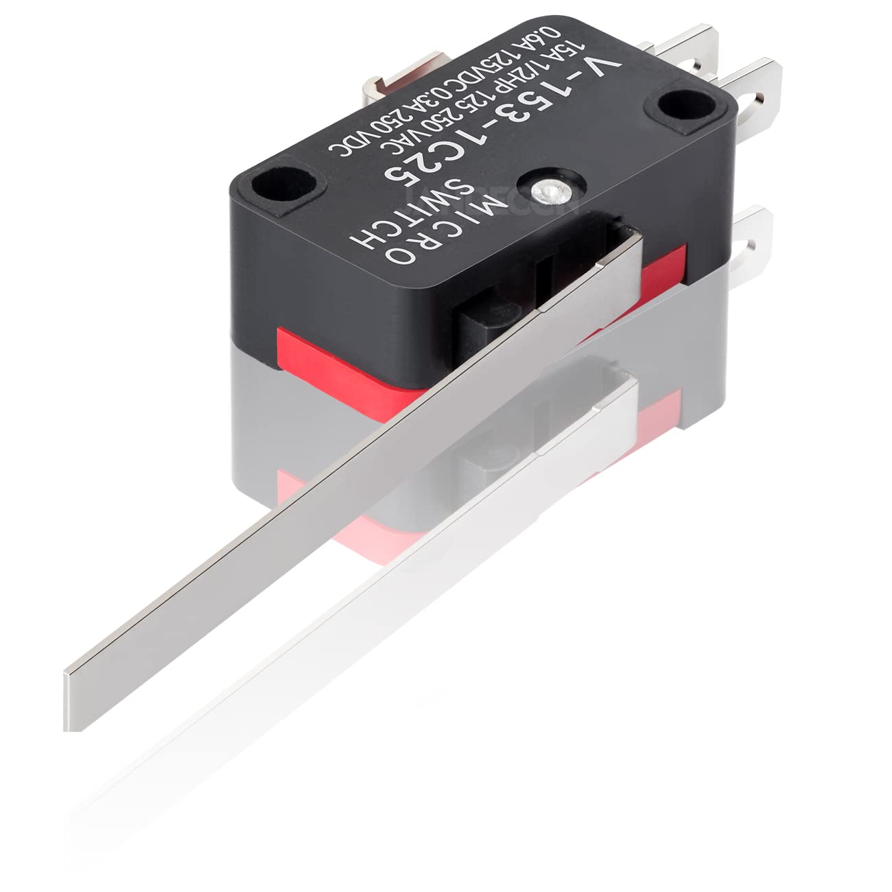
The top button ("Trigger") will be a micro switch inside the top of the press that will activate when the ram is raised, bringing the case into the annealer coil. Once triggered, the 120VDC induction coil will activate via relay (simulated on TinkerCAD by a lightbulb) for the amount of time sent from Arduino B's keypad and then shut off even if the ram is left in the up position. I didn't want the loop reheating the same case if left for too long. The relay completely isolates the induction coil from the loop until the system is reset.

Bringing the ram into the down position, and cycling in a new brass case, will trip another micro switch at the bottom of the stroke ("Reset") which unlocks the trigger pin again as well as doing a plus up on the case counter on Arduino A's LCD.

The ping and pong of the micro switches can continue up to 9999 times to have a solid count on the LCD if one chooses, I never batch more than 200 pieces of brass usually, but I like symmetry, hence why the counter is 4 digits and 6 blanks on either side.

Once you are satisfied with the count, there is another button ("Reset") that is next to the light bulb relay on TinkerCAD, and will just be mounted on my press station for real, that will clear out the count and bring it back to "0000".

Have noticed that it runs an little slow currently and the buttons need to be held in order to move along the program, but I can't confirm if that is issues within the code or just my computer and internet match-up.

I will soon be actually building this so if there is a glaring issue, please let me know what to address before I put it to perf/PCB. The actual device will likely be with Nanos.

I will say, I am truly impressed that I was able to come up with this, making the essentially "stop and wait" without digitally stopping the loop with a wait function that freezes the program in my minute experience. Very incredible what these controllers are capable of

Arduino A Code;

#include <Adafruit_LiquidCrystal.h>

const int LED = 6;
const int PowerSupply = 8;
const int Clear = 7;
const int TriggerRelay = 3;
const int Trigger = 5;
const int Reset = 4;
const int ResetRelay = 2;

Adafruit_LiquidCrystal lcd_1(0);

char currentCountValue[4];
int buttonState=0;
int d1=0, d2=0, d3=0, d4=0;
unsigned int integerValue=0;
unsigned int integerMil=0;
char incomingByte;

void setup() {
  Serial.begin(9600);
  pinMode(LED, OUTPUT);
  pinMode(PowerSupply, OUTPUT);
  pinMode(Clear, INPUT);
  pinMode(Trigger, INPUT);
  pinMode(Reset, INPUT);
  pinMode(TriggerRelay, OUTPUT);
  pinMode(ResetRelay, OUTPUT);

  lcd_1.begin(16, 2);
  
  displayCountEntryScreen();
}

void loop() {
  
  buttonState = digitalRead(Trigger);
  if (buttonState == HIGH) { 
  digitalWrite(PowerSupply, HIGH);
    delay(integerMil);
    digitalWrite(PowerSupply, LOW);
    digitalWrite(TriggerRelay, HIGH);
    digitalWrite(ResetRelay, HIGH);
  digitalWrite(LED, HIGH);
    
  }
    
  buttonState = digitalRead(Reset);
  if (buttonState == HIGH) { 
    digitalWrite(TriggerRelay, LOW);
    d1=d1+1;
    if(d1>9){d1=0; d2=d2+1;}
    if(d2>9){d2=0; d3=d3+1;} 
    if(d3>9){d3=0; d4=d4+1;}  
    if(d4>9){d4=0;} 
    
    
  	digitalWrite(LED, LOW);
  	digitalWrite(ResetRelay, LOW);   
 
  }
  
  buttonState = digitalRead(Clear);
  if (buttonState == HIGH) { 
    d1=0, d2=0, d3=0, d4=0;

  }
  
   if (Serial.available() > 0) {
    integerValue = 0;
    integerMil = 0;
    while(1) {
      incomingByte = Serial.read();
      if (incomingByte == '\n') break; 
      if (incomingByte == -1) continue;
      integerValue *= 10;
      integerValue = ((incomingByte - 48) + integerValue);
      integerMil = (integerValue +35);
    }
    Serial.println(integerMil);

   }

lcd_1.setCursor (0,0);
lcd_1.print(" CASES COMPLETE ");
lcd_1.setCursor(6,1);
lcd_1.print(d4);
lcd_1.print(d3);
lcd_1.print(d2);
lcd_1.print(d1);
  
}

void displayCountEntryScreen()
{
  clearScreen();
  lcd_1.setCursor(0,0);
  lcd_1.print(" CASES COMPLETE ");
  lcd_1.setCursor(0,1);
  lcd_1.print("      0000      ");
}


void clearScreen()
{
  lcd_1.setCursor(0,0);
  lcd_1.print("                  ");
  lcd_1.setCursor(0,1);
  lcd_1.print("                  ");
}

Arduino B Code;

#include <Adafruit_LiquidCrystal.h>
#include <Keypad.h>

char currentTimeValue[3];
int currentState = 1;
int timerSeconds = 0;
int lpcnt = 0;

const byte rows = 4;
const byte cols = 3;

char keys[rows][cols] = {
  {'1','2','3'},
  {'4','5','6'},
  {'7','8','9'},
  {'*','0','#'}
};

byte rowPins[rows] = {11,10,9,8};
byte colPins[cols] = {7,6,5};

Keypad keypad = Keypad(makeKeymap(keys), rowPins, colPins, rows, cols);

Adafruit_LiquidCrystal lcd_1(0);

void setup()
{
  Serial.begin(9600);
  lcd_1.begin(16, 2);
  
  displayTimeEntryScreen();
  
  currentTimeValue[0]='0';
  currentTimeValue[1]='0';
  currentTimeValue[2]='0';
  showEnteredTime();

}

void loop()
{
 
  int l;
  char tempVal[3];
  
  char key = keypad.getKey();
  
  if (int(key) != 0 and currentState == 1) {
    
    switch (key) {
      case '*':
      	currentTimeValue[0]='0';
     	currentTimeValue[1]='0';
      	currentTimeValue[2]='0';
      	showEnteredTime();
      	currentState = 1;
      	lpcnt = 0;
      	timerSeconds = 0;
      	break;
      
      case '#':
      	Serial.println(currentTimeValue);
      	break;
      
     
      default:
      	currentTimeValue[0] = currentTimeValue[1];
      	currentTimeValue[1] = currentTimeValue[2];
      	currentTimeValue[2] = key;
      	showEnteredTime();
      	break;
    }
  }
}

void showEnteredTime()
{
  lcd_1.setCursor(6,1);
  lcd_1.print(currentTimeValue[0]);
  lcd_1.print(".");
  lcd_1.print(currentTimeValue[1]);
  lcd_1.print(currentTimeValue[2]);
}


void displayTimeEntryScreen()
{
  clearScreen();
  lcd_1.setCursor(0,0);
  lcd_1.print(" ANNEALING TIME ");
  lcd_1.setCursor(0,1);
  lcd_1.print("      0.00      ");
}

void clearScreen()
{
  lcd_1.setCursor(0,0);
  lcd_1.print("                  ");
  lcd_1.setCursor(0,1);
  lcd_1.print("                  ");
}

TINKERCAD Brass Annealer

do you know that this library has a simple .clear() function?

Continual use of the clear instruction will be displayed as repeated blanking of the complete screen, then having to completely rewrite the entire screen.
This results in the screen flashing or flickering.

Clearing the part of the display that needs updating just before updating does not cause this annoying flickering.

Tom.... :smiley: :+1: :coffee: :australia:

1 Like

Actually the clearScreen() is not needed, since you are overwriting the entire display line.

If you want to save a bit of ram memory, use the library's clear() function, and remove the leading and trailing spaces in the text. You can also use the F() macro so that print takes the text from program memory instead of ram.

void displayCountEntryScreen()
{
  lcd_1.clear();
  lcd_1.setCursor(1, 0);
  lcd_1.print(F("CASES COMPLETE"));
  lcd_1.setCursor(6, 1);
  lcd_1.print(F("0000"));
}

There is no reason to print the "CASES COMPLETE" line in loop, that will remain on the display until you either clear the display or overwrite the text.

The code will also be a very slight bit faster if you only update the count on the display when the value changes, but with your code that will be unnoticeable, and might even cause problems since you are not debouncing the buttons.

If the intent is to eventually combine the two codes into a single sketch, the clear/trigger/reset switches can be wired as part of the keypad matrix, saving you some pins on the Arduino.

A few more I/O pins can be opened up if a quadrature encoder (using only two pins) is used to set the time with a simple add/subtract method - assuming annealing times won't vary from case to case in a batch.

  d1 = d1 + 1;

Shorthand form is:  d1 += 1;

One area really stands out.

They are capable of 10 to 100 times more than you are asking of them. Yet you are using 2.

One Nano could do both these tasks easily. Using two makes the whole project significantly more complicated and difficult because you need to get the Nanos to communicate with each other.

So why did you use 2 Nanos? If it was because the coding was too difficult, I suspect that's just your inexperience. The extra coding required to get the two to communicate has made it more complex and difficult than it would have been if you had been able to use a single Nano. The forum can help you fix this.

If it was for some hardware reason, I suggest you give more details. You have posted no schematics or details of the components used.

Thank you for those points, I may move the count clear function to the keypad and get rid of that button but I don't know if/how it might be possible to move the trigger and reset to the keypad since they will be limit switches (see below) which will be mounted inside the structure for the press ram and will activate when the main plate has reached the top and bottom of the stroke.

Now that I think about it, it would be overly complicated since most keypads don't have the diodes needed to allow multiple switches to be pressed at the same time. You are nowhere near running out of pins on the Nano, better to leave the switches separate. In case you have not run across the information, analog pins A0 to A5 on the Nano can also be used as digital pins, so you still have four of those unused.

Did the TinkerCAD link not work?

Not to be rude but I'm not sure of the added complexity, once the time has been entered and the "#" key pressed, it's Serial.println as a 3 digit number (5.80 seconds= 580, 1.50 seconds= 150, etc.) and then the other module pulls that value in and converts it into 4 digit milliseconds (580 becomes 5800, 150 becomes 1500) and sets the delay factor for that amount of time.

 if (Serial.available() > 0) {
    integerValue = 0;
    integerMil = 0;
    while(1) {
      incomingByte = Serial.read();
      if (incomingByte == '\n') break; 
      if (incomingByte == -1) continue;
      integerValue *= 10;
      integerValue = ((incomingByte - 48) + integerValue);
      integerMil = (integerValue +35);
    }
    Serial.println(integerMil);

Granted, I do intend to try to clean things up some and possibly bring it back down to 1 unit. It went off into a 2 unit setup when I was first starting out and using a wait function to freeze the loop so that the loop wouldn't activate the induction coil again on the same piece of brass when it came back around

void buttonWait(int Reset){
  int buttonState = 0;
  while(1){
    buttonState = digitalRead(Reset);
    if (buttonState == HIGH) {
     lcd_1.setCursor(6, 1);
     lcd_1.print(cycles);
     cycles += 1;
     digitalWrite(LED, LOW);
      return;
  
    }
  }
}

That basically locked everything up, even if there wasn't an active "Trigger" it wouldn't allow input. Introducing a second unit solved that issue so I just ran with it even after removing the buttonWait.

Yes, the link works. None of the information the forum needs is there, but the link does work.

Have you read the forum guide yet?

No, it didn't solve the locking up issue, it sidestepped the problem and doubled the hardware to achieve it.

Is the second LCD screen there for the same reason?

You might want to do some research on state machines, that is a common way of implementing tasks like this. Also look into detecting when an input changes state, as opposed to basing your actions on the current state (HIGH or LOW) of an input. Button de-bouncing can also be important, but I don't see a need for that in your code, because of the other time-consuming code in loop().

You have a fairly straightforward sequence of events:

1 > wait for "reset" switch to transition from active to inactive (indicating lever is being raised)
2 > now wait for "trigger" to transition to active state
3 > activate annealing coil
4 > wait for completion of annealing and deactivate coil
5 > wait for "reset" switch to transition to active state
6 > increment counter
7 > return to step 1

During step 1 would be the time when you are checking for any keypresses on the keypad, in which case you go into a separate sequence of steps for entering data from the keypad, again returning to step 1 when data entry is complete.

You could also store the time value for the annealing coil in EEPROM, so that you don't have to re-enter the data every time you power up the Arduino.

I will look into it especially given your description of the process, I had tried working state changes briefly which was when I brought in buttonWait because of the reactivation when bringing the ram down. Having these conversations now leads me to want to try edge detection again so that the release of that microswitch takes on the role of the bottom switch maybe. Like I said, I brute forced my way through a fair amount to just get it working and prove the concept to myself. Now is time to slim it down and make it sexy before going through building the real thing.

I have seen EEPROM used by others in their projects but haven't gotten into understanding it myself so will likely my next learning topic.