Brushed Motor Interference

Hello all,

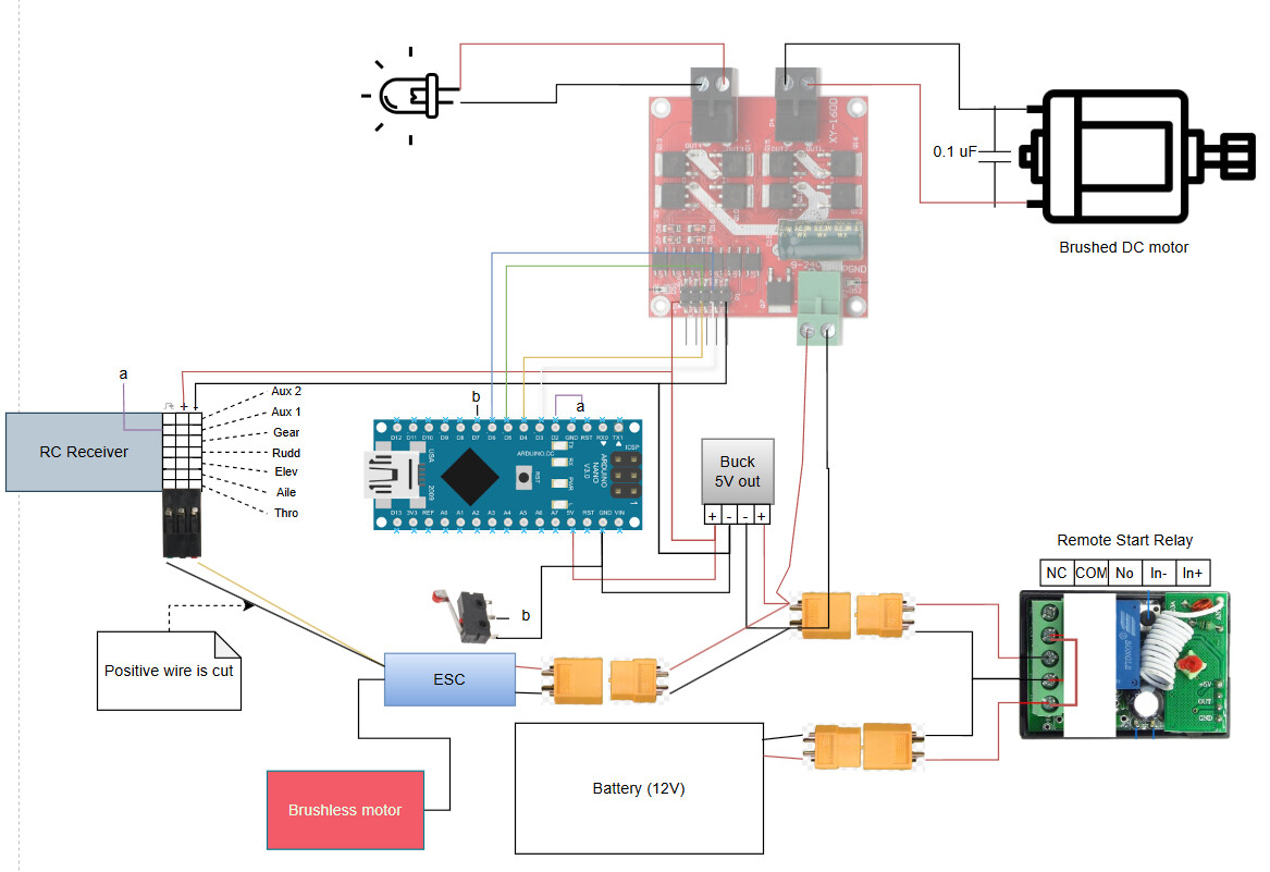
I am working on an RC submarine with an Arduino controlled ballast pump.
The goal: to control the ballast pump with an RC transmitter through the Arduino.
The problem: there are interruptions that cause the motor to hitch when running in one direction and not the other.
My hypothesis: arcing brushes in the motor cause some sort of interference with the Arduino.

Here is my wiring diagram:

Here is a functional version of my code with only relevant features included:

int RCValue;
#define RCPin 2
int motor1pin1 = 3; // White wire, Goes to IN1
int motor1pin2 = 4; // Yellow wire, Goes to IN2
int motor2pin1 = 5; // Green wire, Goes to IN3
int motor2pin2 = 6; // Blue wire, Goes to IN4

void setup() {
  // put your setup code here, to run once:
  Serial.begin(9600);
  
  // Pump Motor & LED
  pinMode(motor1pin1, OUTPUT); // Controls IN1
  pinMode(motor1pin2, OUTPUT); // Controls IN2
  pinMode(motor2pin1, OUTPUT); // Controls IN3
  pinMode(motor2pin2, OUTPUT); // Controls IN4
  

}

void loop() {
  // put your main code here, to run repeatedly:
  delay(100);
  // RC Input
  RCValue = pulseIn(RCPin, HIGH); // Read RC Value
  Serial.print(", RCValue:");
  Serial.println(RCValue);
  Serial.print("Lower:");
  Serial.print(900); // To freeze the lower limit
  Serial.print(", Upper:");
  Serial.print(2000); // To freeze the upper limit

  if (RCValue > 1700){
    Serial.println("Diving");
    digitalWrite(motor1pin1, LOW);
    digitalWrite(motor1pin2, HIGH);

  } else if (RCValue > 1300){
    Serial.println("Neutral");
    digitalWrite(motor1pin1, LOW);
    digitalWrite(motor1pin2, LOW);

  } else {
    Serial.println("Surfacing");
    digitalWrite(motor1pin1, HIGH);
    digitalWrite(motor1pin2, LOW);

  }

}

And here is an example of what the interruptions in the serial plotter looks like:

Relevant Parts List:

  • Mateksys MBEC6S 5v Buck Converter
  • Gikfun 12V DC Dosing Pump Peristaltic
  • DROK DC Motor Driver, L298 Dual H Bridge
  • JR 70 MHz Receiver
  • Arduino Nano (Official)

What I tried: I tried adding a 0.1 uF ceramic disc capacitor across the motor terminals to mitigate electrical noise. There seemed to be no effect and the issue persists. I also tried twisting the wires leading to the DC motor.

Observations:

  • The RC receiver can run servos and a brushless motor with no issue even while these interruptions are happening. I think it's safe to say the receiver is not the problem.
  • Interruptions cease when disconnecting the motor.

I am looking for ideas on how to fix these interruptions. I'm willing to try different solutions and answer any questions you have. I am an amateur Arduino creator and I look forward to learning about best practices.

I'm not sure how you see/feel/sense this "hitch".
So if you just connect motor driver pins to HIGH/LOW or LOW/HIGH without arduino, does it misbehave?

Does the posted code actually demonstrate the motor problem?

Test the motor with the simplest possible code that will make it run forward and backward.

what the interruptions in the serial plotter looks like

The dips are timeouts in pulseIn(), and are meaningless as measurements.

Switch to brushless motors. Change ancient L298 for modern MOSFET design.

Somehow get to the metal frame of the motor and ground it to the system ground. It will be your best shielding for arcing of the motor brushes.

Yes. I made this abridged version of the code to eliminate variables. I will try and even simpler version of the code like you suggested and let you know how it goes.

I will give this a try and let you know how it goes

Any recommendations?

To clarify, the motor "hitches" when it suddenly changes direction during one of these interruptions. In other words, the PWM jumps to 0 momentarily and the motor suddenly changes direction as a result

Recommendations for what?
If you meant motor drivers, then check the specs on TB6612FNG. Here are a few more

Part Number Max Current Peak Current Voltage Range Notes
TB6612FNG 1.2A 3.2A 2.5–13.5V Popular, low-RDSon, efficient
DRV8833 1.5A 2.7A 2.7–10.8V Compact, 1.5A continuous, supports slow decay
MX1508 1.5A ~2A 2–10V Very cheap, low-end alternative
and
Higher Performance are
Part Number Max Current Peak Current Voltage Range Notes
--- --- --- --- ---
DRV8871 (single) 3.6A 6A 6.5–45V TI driver, single H-bridge, great for one motor
DRV8848 2A 4A 4.5–18V Efficient, dual H-bridge
MC33926 3A 5A 5–28V Robust, overcurrent protected, single bridge
VNH5019 12A 30A 5.5–24V High power, dual bridge versions exist

:warning: Things to Watch For:

  • MOSFET-based drivers like the TB6612FNG and DRV8833 are efficient (low heat) compared to BJT-based ones like L298N.
  • If your application involves PWM control, ensure the driver supports fast switching and decay modes.
  • Check for thermal shutdown , overcurrent protection , and voltage clamping if you need robustness.

I wrote the following code to run the motor in both directions:

int motor1pin1 = 3; // White wire, Goes to IN1
int motor1pin2 = 4; // Yellow wire, Goes to IN2
int motor2pin1 = 5; // Green wire, Goes to IN3
int motor2pin2 = 6; // Blue wire, Goes to IN4

void setup() {
  // put your setup code here, to run once:
  Serial.begin(9600);
  
  // Pump Motor & LED
  pinMode(motor1pin1, OUTPUT); // Controls IN1
  pinMode(motor1pin2, OUTPUT); // Controls IN2
  pinMode(motor2pin1, OUTPUT); // Controls IN3
  pinMode(motor2pin2, OUTPUT); // Controls IN4
  

}

void loop() {
  
  Serial.println("Neutral");
  digitalWrite(motor1pin1, LOW);
  digitalWrite(motor1pin2, LOW);
  
  delay(1000);

  Serial.println("Diving");
  digitalWrite(motor1pin1, LOW);
  digitalWrite(motor1pin2, HIGH);

  delay(10000);

  Serial.println("Neutral");
  digitalWrite(motor1pin1, LOW);
  digitalWrite(motor1pin2, LOW);

  delay(1000);
    
  Serial.println("Surfacing");
  digitalWrite(motor1pin1, HIGH);
  digitalWrite(motor1pin2, LOW);

  delay(10000);

  }

The motor ran in both directions without any interruptions.

Thank you for your suggestion! I soldered the ground terminal on the motor to the case and the issue persists.

Thank you for the suggestions. I will look into this.

It must go directly to your system common ground, not through a bunch of circuit boards and connecting wires! You do have a common point where all grounds are connected, don't you?

Your code posted here doesn't use pwm.
If pwm goes to zero, it doesn't change direction of motor.
You didn't answer how it behaves connected directly to HIGH/LOW.

How are you getting the radio signal? Some sort of floating waterproof carrier for the receiver with antenna exposed through a waterproof opening? What wiring from there to the sub? I was thinking CAT6.

A better approach is this one.

Something else might be causing the pulseIn() timeouts.

I see now what I did wrong. I will connect the motor casing to common ground and try again.

I am using a 70mHz RC radio transmitter and receiver. I want my sub to be untethered and lower frequencies like 70mHz perform better through water than 2.4 GHz.

I have some RC equipment, all are 2.4 GHz, never heard of 70 mHz, is it common in RC stores?